Storage tanks and secondary containment

Note that this post is about routes of the 1970's and later as secondary containment was not absolutely required before that time.

To add realism to the industrial parts of our layouts, we need to be sure and add some type of secondary containment to the storage tanks containing hazardous fluids, particularly oil. EPA SPCC regulations (https://www.epa.gov/oil-spills-prevention-and-preparedness-regulations) require a containment structure around tankage equal to 100% of the tank storage capacity plus the maximum expect amount of rainfall in a 24 hour period. This secondary containment is generally a continuous earthen berm around the tankage which, with the height of the berm and enclosed area, provides the necessary volume to contain the required volume. Small tanks can have other types of containment; concrete boxes, open top metal tanks, etc.

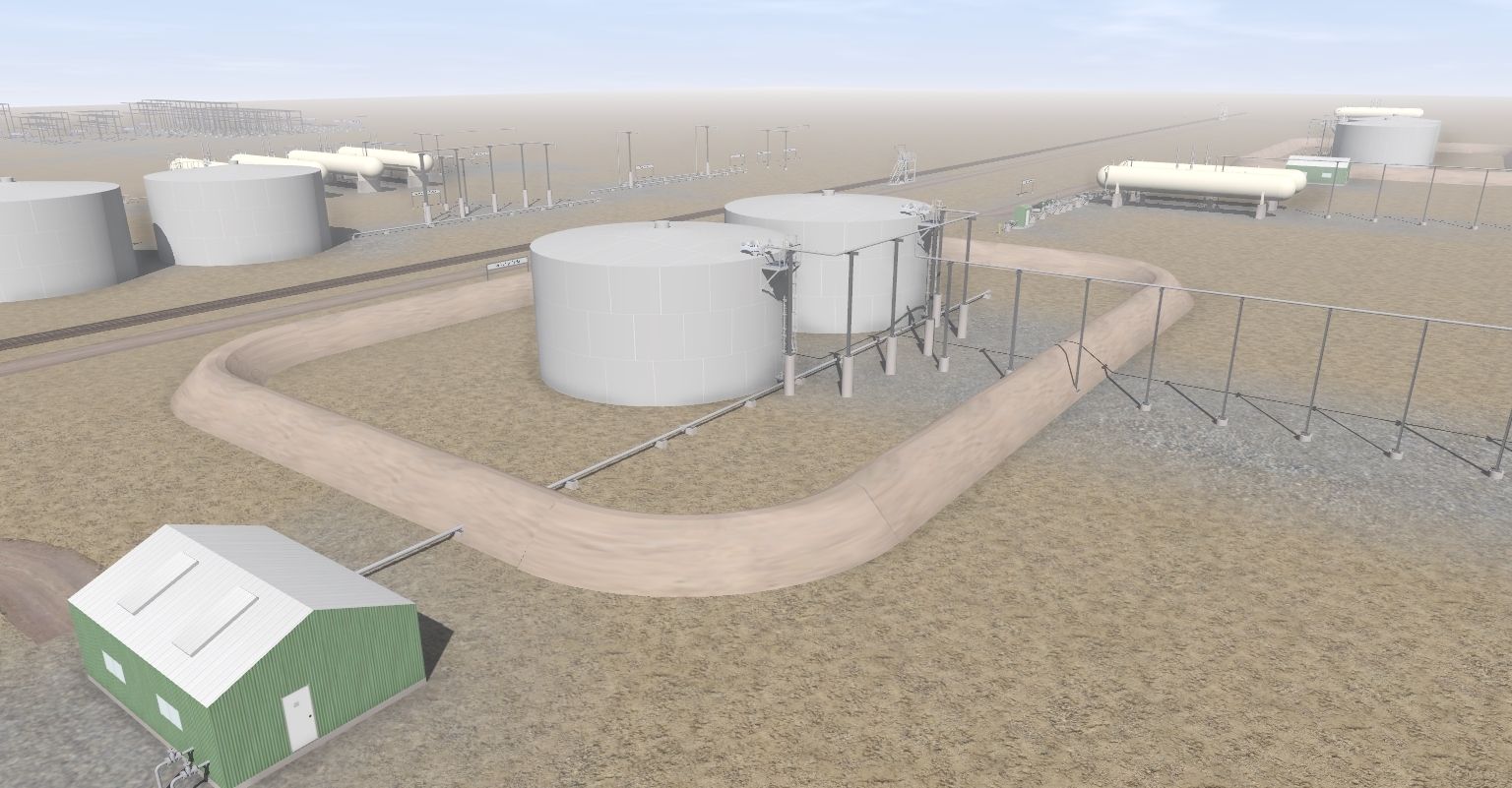
An example of a containment berm around storage tanks is my tank berm spline and tank berm corner objects shown in this screenshot. Each tank has a maximum storage capacity of 2402 m3 for a combine volume of 4804 m3. The berm is 2.25m high and the enclosed area (I went into Surveyor and found the dimension of the berm to be approximately 50m by 75m) of 3750 m2. The contaiment volume of the berm therefore is approximately 8437 m3 which is almost double the required volume. Therefore, the berm meets the requirements of the SPCC regulations.

Tanks-with-containment-berm.jpg


My two berm assets are:

<kuid2:417385:101776:1> Oil Tank Berm corner
<kuid:417385:101833> Oil Tank Berm ver1.1


No, I don't expect everyone to do the above calculations before placing a berm around storage tanks. The calculations just illustrate how the real world works and also to note that my "looks right" berm placement in Surveyor was more than adequate for the purpose.

Not to pick on anyone (but I will) but the fuel storage farm in JR's Fort Liberty route doesn't have and secondary containment and is therefore not very realistic.

Fort-Liberty-tank-farm.jpg


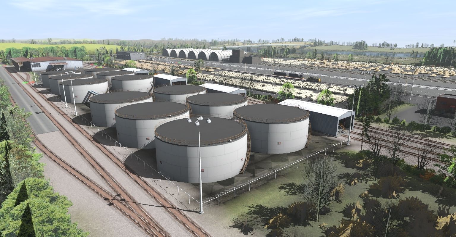
Just a guess, but I think with about half the number of tanks with a berm at the location of the surrounding fence would probably be about right for secondary containment for this tank farm.

I've seen numerous other examples of storage tanks without secondary containment in numerous routes depicting the present era. I know, picky, picky but hey, I'm engineer!

Just a thought to get our routes to be a little more real life.

Take care,
 
Though in general I do agree with you on this topic, there are a few things to keep in mind:
- Rules / Laws differ from country to country, sometimes even from state to state
- Even within those rules, it is not weird that military facilities follow different or simply ignore the rules
- Rules and reality are not always in line :hehe:

I didn't bother reading all the rules, but I would not be surprised if the rules also state that pipes are now allowed to go through a berm (as in your example) but instead have to go over them (as going through them could cause a weakness).
 
I didn't think the USA had an EPA any more :hehe:, but it's great to see some industrial realism coming to Trainz. Are there spline versions as well as the fixed Scenery type, just to make things (literally) more flexible for users?

I once made a self-bunded diesel tank, but it's only 2500 litres in capacity. Just my small contribution to industrial realism.


.
 
Last edited:
DWBennett55, thanks for these assets! I was working on a yard and all I could find was an asphalt-looking berm spline that I had to make corners with by playing with extra spline points. .This looks very handy!
 
Though in general I do agree with you on this topic, there are a few things to keep in mind:
- Rules / Laws differ from country to country, sometimes even from state to state
- Even within those rules, it is not weird that military facilities follow different or simply ignore the rules
- Rules and reality are not always in line :hehe:

I didn't bother reading all the rules, but I would not be surprised if the rules also state that pipes are now allowed to go through a berm (as in your example) but instead have to go over them (as going through them could cause a weakness).

Sorry, sir, but the US military has to follow the same laws as anyone else. See the need for an environmental impact statement for any basing changes; a change of the numeber of aircraft at an airbase or even the change of a practice range site. But above all, the EPA would be all over the US DOD if there was an oil, gasoline, diesel spill that entered "the waters of the United States" which, by the way is usally interpreted and "any" water course.

And as for the variation of rules and regulations between states, yes, they can but the minimum requrements are the Federal regulations by the EPA. As for international regulations, I can hazard a guess (and probably not too much of a wild one) that the Canadian, EU, Australian, NZ, etc. will pretty much be similar to the US rules and regs. Oh, a lot of countries might have similar regs but the key is enforcement and penalty, which in the US anyway can be swift and costly for willful noncompliance.

Next, no the piping going through the berm wall will not impact the integrity of the berm wall as long as the wall is of sufficient width. However, the piping must be not have insulation on it as any fluid can get under the exterior coating and flow through the annular area between the jacket and pipe wall taken up by the insulation. I have installed numerous tanks installation and never had a problem with this arrangement.

To paraprase the EPA Guidlines for SPCC, 40 CFR Ch.1, Para. 112.7(c), the containment system must be capable of containing oil and constructed so any discharge from the primary containment (the tanks) will not escape the (secondary) containment system. Further in Para. 112.7(c.1.i), Dikes, berms or retaining walls sufficiently impervious to contain oil. In other words, building the berm out of beach sand might not be the best idea. Limiting the berm penetrations is, of course, a good idea but elimination of them is not required. Correct design and installation of any berm penetrations is, obviously, necessary and easily done (possibly adding a clay material, bentonite, around the pipe to stop any seepage along the pipe wall). In fact, in all our large bermed areas there was also a drain pipe, with a valve locked closed when not in use, to drain rain water or snow melt (lots of snow melt water) that penetrated the berm or ran just below it. Of course, use of the drain pipe was strictly controlled.

But getting back to the whole concept of the secondary containment; it is to contain any discharge from the tanks and allow prompt cleanup. The contained area is not meant to be a long term storage structure for oil. It is there to prevent a discharge to adjacent water bodies or courses. The area enclosed by the berm is most likely not totally impervious to oil so the clean up of the spill must be pretty darn quick to include the excavation and proper disposal of all contaminated soil and material. Failure to quickly excavate the contaminated soil from the site could lead to ground water contamination and the subsequent cleanup (not easy and with very long term moinitoring requirements). In fact, even with prompt cleanup ground water testing might be required to see if any contamination occurred.

All of the above, to one extent or another, is to be included in the SPCC plan.

Sorry to get so off the topic of "Trainz" but I lived this for many years and had to be at least familiar with the ins and outs of the regulations.

Take care,
 
Last edited:
I didn't think the USA had an EPA any more :hehe:, but it's great to see some industrial realism coming to Trainz. Are there spline versions as well as the fixed Scenery type, just to make things (literally) more flexible for users?

I once made a self-bunded diesel tank, but it's only 2500 litres in capacity. Just my small contribution to industrial realism.

QYcRPIT.jpg

Deane, the asset <kuid:417385:101833> Oil Tank Berm ver1.1 , is the berm spline.

Take care,
 
Evening Gentleman,

Just happened to trip over this thread tonight, and I simply delighted with the Berms you made, have wanted something like this for a long time, but never figured it would come about.......Appreciate your hard work and dedication to the Craft......Only problem is, now that I just downloaded these Rascals, I have to go back and try to make some Changes where possible.......And in this Case, that is a problem I think I'll enjoy having as I make the necessary changes to my Tanks..........
 
Why the pipe through the berm?

The piping in the screenshot above is meant to show the suction pipe to the LACT pumps. Again, LACT stands for Lease Accounting Custody Transfer. This is the measurement of the oil being sold and is done with agreement between the seller and buyer as to how and with what equipment to ensure accuracy of measurement and quality of the oil sold. These LACT pumps, in the facaility which all my main assets are based on, were vertical multi-stage centrifugal pumps. These pumps were choosen because of the potential for very low available suction head to be supplied to the pump. They were better than 10' in length and installed in a "can", sunk into the ground such that the bottom, first, stage had the benefit of the additional feet of head so as to prevent cavitation in the first stage impellar.

However, proper design of the suction piping from the tanks was also critical. The piping must be of sufficient size and with the minimum number of fittings (tees, elbows, etc.) to minimize the head loss through the piping to the pump inlet.

It must be remembered that the design point for the pipeing system is with a very low tank level; probably a foot or so above the tank suction connection to ensure a flooded suction piping. The pumps won't have any difficulty operating at a high tank levels as there will be plenty of suction head.

What about running the piping up, over, and than back down to the pumps? That arrangement would create a vapor pocket and eventually starve the pumps of suction.

What about running the piping below the berm and then back up to the pumps? This adds unnecessary fittings in the suction piping (head loss); adds the possibility of underground corrosion which may go unnoticed for a long time; the "U" shape can lead to the accumulation of solids and possibly water also (both which can help corrosion) and lead to flow restrictions. True, there isn't supposed to be any BS&W (Basic Sediment and Water) in the oil at this point but if that was always true then the BS&W meter wouldn't be needed on the pump discharge. The BS&W monitor, at a set detection level, divertes the pump discharge to the "bad oil" tank to be rerun through a portion of the facility (the heater treaters in our case).

And as for the corrosion possibilities of the pipe running through the berm, yes, that can happen but it will also be easily detected with minimal effort. Correct design and installation of the piping and it's exterior coating will most probably forestall any corrosion in that location.

Anyway, this all this an explanation of why the straight suction header out of the tanks directly to the LACT building.

Take care,
 
:wave: Great info shared here.....One of my interest's is how certain Structures are built and work in unison.....

I just came across an Old Power Company Oil Fired I think, conversion to Gas Fired Plant in So Cal area in process......

Plan out seeing how it ends out in another year or so of construction too see what they do, and what they Scrap after all is said and done, and if the new footprint will be marginally smaller in the land area they have to work in?.....

The other reason, I want to try and take available assets in Trainz and make something similar......

:cool: Thank you for sharing
 
Back
Top