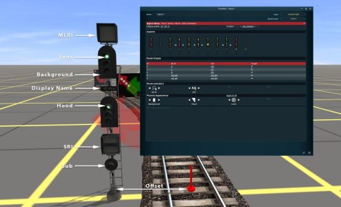
Signal Settings
Common
Display Name
- The display name can be used to display a different identification on the signal ID plate than what is in the signal’s name box.
- Multi line names are split using a space.
- An example of this would be a signal acting as an Indicator to another signal:
- Parent signal is called “SM 205”
- Indicator signal is called “SM 205 IND”
- The display name of the indicator signal can be set to match the parent signal and a separate indicator plate fitted to the signal post.
- The offset value can be adjusted by clicking the left and right arrows to nudge the signal 5cm in either direction.
- You can also click on the number and enter a new value (in cm). Negative numbers position the signal to the left and positive to the right.
- A signal which is re-positioned to the opposite side will display an arrow plate pointing back towards the track to which it applies.
- The outer two dark grey numbers show the maximum distance the signal can be positioned in each direction (currently set at +/- 5m).
- The possible signal indications the signal can give are displayed in this section.
ID
- This is a sequential number to identify the routes for that signal. The first route listed is the default route.
- This column allows you to input the text to be displayed in the Main Line Route Indicator for that route. If no MLRI is fitted then this column will be greyed out.
- Like the MLRI, this column allows you to input the text to be displayed in the Small Route Indicator used for shunting movements. If No SRI is fitted then this column will be greyed out.
- An arrow is displayed next to each route to indicate which target direction to use.
- Clicking on the arrow will allow you to enter the name of a route override target to use.
Main Line and Small Route Indicators (MLRI and SRI)
- Allows the display style of the route indicators to be changed.
- The following options are available:
- Matrix - A 9x9 grid of LEDs forming a single, large character.
- Array - An arrangement of LEDs that form up to two characters.
- Stencil - A backlit cutout capable of displaying two characters.
- On single light signals, the Turnout Unit can be set to display both directions (default) or a single direction.
- Some signals fitted with subsidiary indicators allow offsetting the position to indicate a left or right diverge.
Style settings can be configured to add variety to the signals on the route. An “Apply to All” option is available to copy the style settings to other signals. Note that not all signals support the same settings and so not all signals will be included when clicking “Apply to All” (e.g. DL and SL style settings will not be shared).
Background
- Changes the shape of the background panel on the main lamp heads.
- Allows changing the type of hood fitted to the signal.
- Changes the type of lamp being used for primary lamp heads and turnout indicators.
- Options are:
- Incandescent (default)
- LED
- Some signals have an additional setting which can be changed.
- This is not included when “Apply to All” is clicked
Click the image below to see an overview of the settings and which parts of the signal they relate to.

