Sorry for the delay but Trainz is not a high priority in my life right now. It's setting on the back burner and has been for 6 months or so and probably will continue to be for a few more. I did find some time recently to finish some new especs for an old friend's DHR locos and I have committed to some forensic scripting work for another Trainz content maker but apart from these I have other more pressing things to work on.Well, that sounds good - but I also need my track plan overlaid on the real world imagery as I am creating it, which poses a problem. To my knowledge no CAD program lets me do this. TransDEM is made to, only its editor thinks solely in terms of straight lines, not arcs.
Do you know of a workflow I can use for several hundred miles of track, to overlay it in CAD over sateĺlite imagery?
Your quote: "To my knowledge no CAD program lets me do this." - As to your personal knowledge I can't attest to that but personally I have done this using various cad programs over the past 15 to 20 years so I'll have to disagree with your premise at least.
In any case many cad programs do allow you to import an image file as a background and "trace" lines or any other drawing objects over it. I use turbocad - an old ver 9.0, also an old version of Autocad, and am testing out a free open source cad program called FreeCAD. While I haven't used FreeCAD for any production work it has a ship design module and as a retired naval architect I'm hoping I find it rather interesting to play around with. CadRail is another small and limited 2.5 D drafting program I use a lot. It's designed specifically for model train layout design so has a few features tailored for track work design. I use it for some basic 2D drafting and for Trainz I can make full sized drawings of real railroads with it. All of these cad programs I've mentioned allow you to import an image file as a background and then trace out a drawing over it.
I've done my home Trainz layout, the EBTRR in it. A small 3'ng railroad that stopped commerical service in 1956 almost 80 years after the main was built. Most of the main line track is still on the ground but unusable. With 32 miles of main line and 10 branch lines and spurs, it's over 100 miles of track lines, 3 main yards and 1 with several miles of standard, dual and ng track. I have to admit I did not trace the track route (current one I'm using) overtop image files in the cad program(s). I created the dxf files from data take from the EBT's 1919 survey maps since they inidcate the station number (feet from along the main from a reference point in Mt Union, PA) of each curve start and end point, each turnout point and every grade change, crossing an bridge locations along the main and branch lines along with other interesting things like the radius and central angle of each curve and elevations at each grade change and vertical transition curves.
However when I 1st started the route back in TRS2004 I did import images of the Tiger data into my cad program and used that to trace out the track route using only straight tangent sections and circular arcs since that is what the EBT used when laying the track on grade. However any drawing tool was available and transition curves could have been added if I wanted - for some reason - to add them in. Now I limit tracing image files to primarily working with the yard trackage in some locations. I have modified the traced drawings based on my own limited surveys taken in the field or descriptions of other peoples work.
The approach I used is outlined in general terms below and I've used basically this approach in many application where I've traced over images - not just for track work in Trainz:
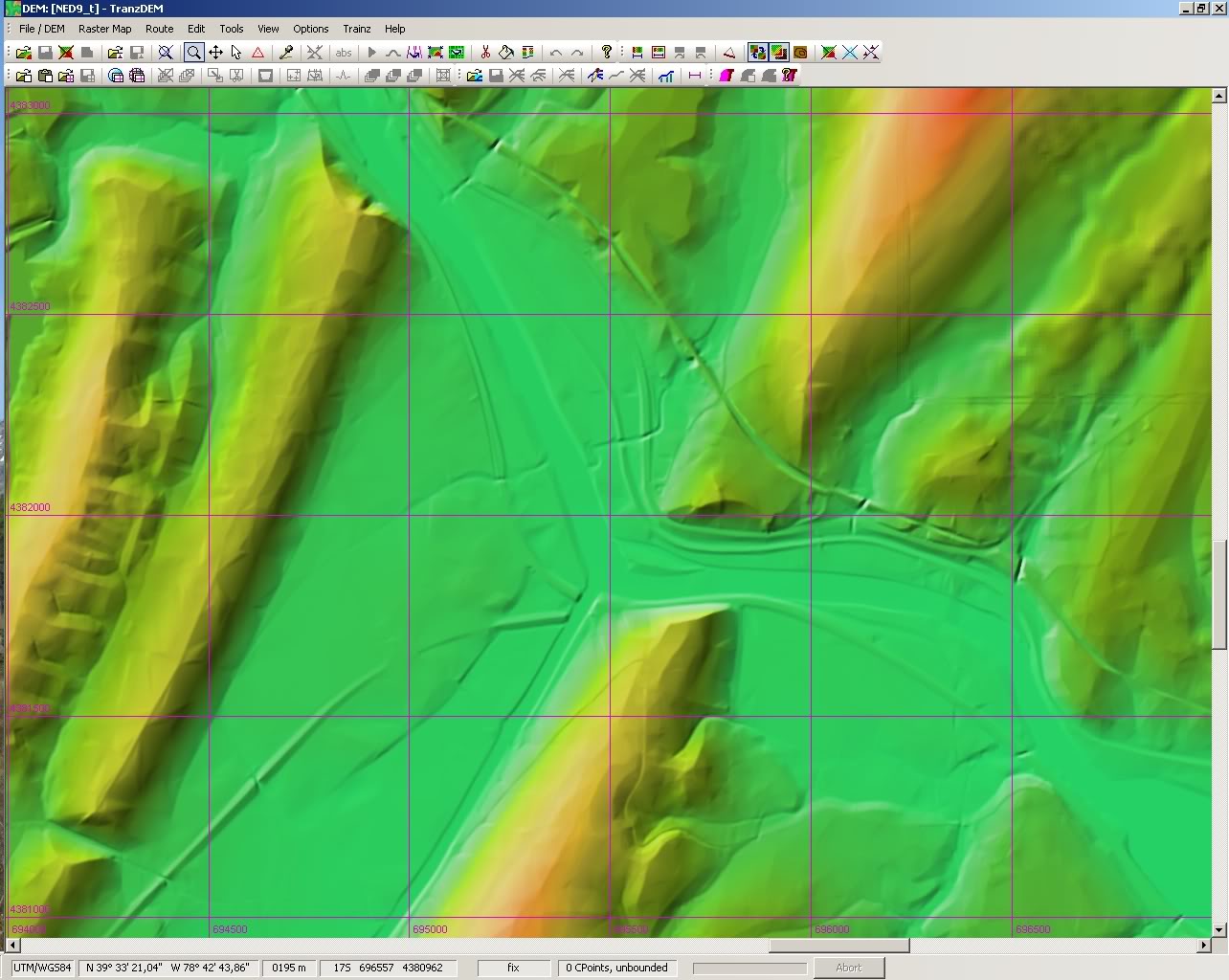
1) obtain an image file that is geo referenced to the terrain defined by the DEM you are using. A UTM projection is the most suitable. I'm not sure how ortho imagery compares with this projection.
2) import the image file (must be in a format supported by the cad program - conversion utilities do abound though)
3) geo-referencing is a problem typically you will have to position the image properly so the coordinate grid used in the dwg aligns with the UTM grid of the image for the zone in question. Cad programs typically allow you to scale, translate and rotate complete drawings or any objects within the drawing which sometimes is necessary to correct alignment problems
4) the dwg units should be in meters but this can be corrected after the fact. If the image file is a full size UTM projection you won't have to make any major adjustments later.
5) using the tools available create the track route over the image file
6) scale and units aren't too important since the cad program allows you to scale the drawing afterwards.
7) export a dxf file of the drawing and import it into TransDEM
"TransDEM is made to, only its editor thinks solely in terms of straight lines, not arcs." Well the cad capabilities are I'll grant you not up to the standards of a 2d drafting program. But I don't believe that was Roland's aim here. It does allow you to pegout a route over the displayed DEM or an imported image of the area that is sufficient to allow filtering of the trainz baseboards created so you can limit their number and confine them to areas where the track is to be laid. I think you're asking a lot more for the 30 USD or so you paid for TransDEM than you're entitled to IMHO. The little cad program for model railroad layout I mentioned above is IIRC 95 USD. Updates are cheaper and the 1st version I got was probably less than 50 USD. So TransDEM with a better cad package in it should be worth a bit more than 30 USD you paid.
I'll also note in passing: Tracing over orthro pics or such won't necessarily allow you match the radius or start and end points or where the transitions start and end either to the accuracy you might be thinking of. I've tried using the push pins in google earth pro (I've an early post in this thread about this) and it's just an approximation as good or maybe better than many use in Trainz route generation. So I'm not sure why you need to match some mathematical cuvre to the degree of accuracy you think you might be able to achieve here. You'd probably have to do your own calculations for the lengths of the transition curves to use in your drawing. These could be based on a "known" speed limits, superelevation and curve radius. Without track diagrams some or all would of this be based on estimates or maybe just "guesstimates" of what you see in the images.
I guess easy is in the eyes/mind of the user but I've been doing this - creating track files outside surveyor - for many years.Nahhh ... That just aint' gonna happen to easily get a program to lay Trainz track for you ... Get used to laying track the good ol' fashioned, taking 6 years of your life, way !
Bob Pearson
Last edited:
 I have found that most 2.75% grades are in total error, and by using the outermost edge of the tracing line, gives you a 0.10% to 0.50% gradient ... rarely does a RR grade exceed 1.00%