Weird signal behavior - why?

MSGSapper

Trainz route developer
I am testing my New England Coastal route and have run into a problem. I have a <kuid2:45324:24341:3> Searchlight Signal 06-LD Gantry that is showing incorrect signal lights on the track. I have checked to make sure all track is connected correctly and it is. Here is what I am seeing:

Signals.jpg


As you can see the junction is not set to the left diverging path so the lower signal should be red. I have tried moving the signal closer and further away from the junction throw switch but the lights remain the same.

Any idea what is causing this and how to fix it?

Bob
 
it is reading the next signal and is an appropriate aspect for the straight route. it is saying approach the next signal prepared to diverge, if you look at your screenshot you can see the next switch set to diverge, so there is no problem here.
The problem is the lower signal, which is for the left diverging track, not the upper signal. That lower signal should be red.

Bob
 
that's just not how they work. the aspect is "approach diverging" because the next signal is red over green for diverging clear. this is prototypical and intended operation. if the next signal were clear indicating a straight on path, then the signal would show green over red.
 
that's just not how they work. the aspect is "approach diverging" because the next signal is red over green for diverging clear. this is prototypical and intended operation. if the next signal were clear indicating a straight on path, then the signal would show green over red.
I am sure it is crystal clear to you, and I appreciate your trying to help me, but maybe I just don't understand how this is supposed to work with these particular gantry signals. See the following image:

Signal1.jpg


I have a lot of signals on this large route but only have seen this issue in just a couple of cases. In the image you will see three left diverging tracks which all end in dead end tracks which I put an "invisible signal" at the end of so my gantry signals work correctly. Here is what is shown:

1. In the first gantry signal past the locomotive the lower signal shows red as I see throughout my route in similar situations. Green for the upper part.

2. In the second I see a green for the lower part of the signal. For the upper part of the signal I see yellow. The upper part makes sense to me since the third signal shows red in the upper part. The lower part (green) makes no sense to me since I don't see this elsewhere on my route and I have not thrown the switch to have the locomotive go on the left diverging track.

3. In the third signal, lower part, I see a yellow. In the upper part I see red which makes sense. The lower part (yellow) makes sense since I threw the swith to have the loco go on the left diverging track.

At this point I am somewhat confused about what I see here, but in the end even if I don't undertsand this will probably just leave things be and accept what appears weird to me.

Bob
be careful what you say bob NS37 Designed and Built those signals for the game and Knows how things work to IRL and the Prototype operations of them..
Second 3 switch is Set for the Diverging Route and are showing Approach Medium or Limited Clear.. you start out with a Clear signal then Progress to an Approach Medium Signal which is set for the Diverging Route with the 3 Switch being set for the Diverging Route......
 
I am sure it is crystal clear to you, and I appreciate your trying to help me, but maybe I just don't understand how this is supposed to work with these particular gantry signals. See the following image:

Signal1.jpg


I have a lot of signals on this large route but only have seen this issue in just a couple of cases. In the image you will see three left diverging tracks which all end in dead end tracks which I put an "invisible signal" at the end of so my gantry signals work correctly. Here is what is shown:

1. In the first gantry signal past the locomotive the lower signal shows red as I see throughout my route in similar situations. Green for the upper part.

2. In the second I see a green for the lower part of the signal. For the upper part of the signal I see yellow. The upper part makes sense to me since the third signal shows red in the upper part. The lower part (green) makes no sense to me since I don't see this elsewhere on my route and I have not thrown the switch to have the locomotive go on the left diverging track.

3. In the third signal, lower part, I see a yellow. In the upper part I see red which makes sense. The lower part (yellow) makes sense since I threw the swith to have the loco go on the left diverging track.

At this point I am somewhat confused about what I see here, but in the end even if I don't undertsand this will probably just leave things be and accept what appears weird to me.

Bob


Yes this is all correct. When a signal has multiple heads, it is to convey more information to the train crew about the situation ahead. You mustn't get confused into thinking the 2 lights can only mean top light for straight ahead and bottom light for the diverging route, while that is generally the message conveyed by the signal in most cases, it is not how the signal operates. If a signal has 3 heads for example, it doesn't mean there is a 3 way switch or anything like that, it just gives ability to display more information.

In the situation above where you have a 2 head signal with a 2 head signal beyond there is the ability to show more information than you could have with a single head. The signal is displaying an "approach diverging" (yellow on top = approach, lower head anything but red meaning diverging); the train needs to approach the next signal prepared to take the diverging route. It is also worth noting that this could be a valid signal indication even if the switch was thrown, assuming you have another signal protecting a junction along that line. The idea that the top light is for one direction and the bottom light for the other direction is a misconception.
 
Last edited:
Yes this is all correct. When a signal has multiple heads, it is to convey more information to the train crew about the situation ahead. You mustn't get confused into thinking the 2 lights can only mean top light for straight ahead and bottom light for the diverging route, while that is generally the message conveyed by the signal in most cases, it is not how the signal operates. If a signal has 3 heads for example, it doesn't mean there is a 3 way switch or anything like that, it just gives ability to display more information.

In the situation above where you have a 2 head signal with a 2 head signal beyond there is the ability to show more information than you could have with a single head. The signal is displaying an "approach diverging" (yellow on top = approach, lower head anything but red meaning meaning diverging) meaning the train needs to approach the next signal prepared to take the diverging route. It is also worth noting that this could be a valid signal indication even if the switch was thrown, assuming you have another signal protecting a junction along that line. The idea that the top light is for one direction and the bottom light for the other direction is a misconception.
OK, thank you for the explanation and clarification.

Bob
 
I'm wondering if the signals are too close to the switches and/or the switches trigger radius is defaulted to 20 meters. Try setting the switch radius to .5 meter.
 
In no case in Canada does a mast with multiple targets indicate that the top signal is for the main line and the others are for diverging lines.

This is absolutely false.

Multiple target signals indicate whether a turnout is straight or reversed and what the speed is for passing through that turnout.

And of course, whether the dedicated track is occupied or not.

The more targets there are, the more information is provided.

And even more possibilities regarding speeds.

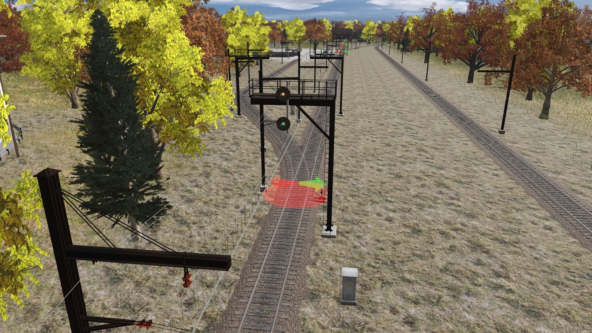
A mast with two targets showing yellow over green is a suitable signal. It is given for access to the main line to indicate a clear track with a medium speed approaching the next signal.

Of course, with a mast with two targets, you will never have a green light in the top target for access to the diverging line.

Why? Simply because passing through a reversed turnout must be done at reduced speed, and it is the second target that will indicate this. You will likely get a red-on-green signal if the track is clear and the next signal is permissive. In other cases, you will get a red-on-yellow, red-on-yellow flashing signal for access to the diverging track that is clear but the next signal is not permissive.

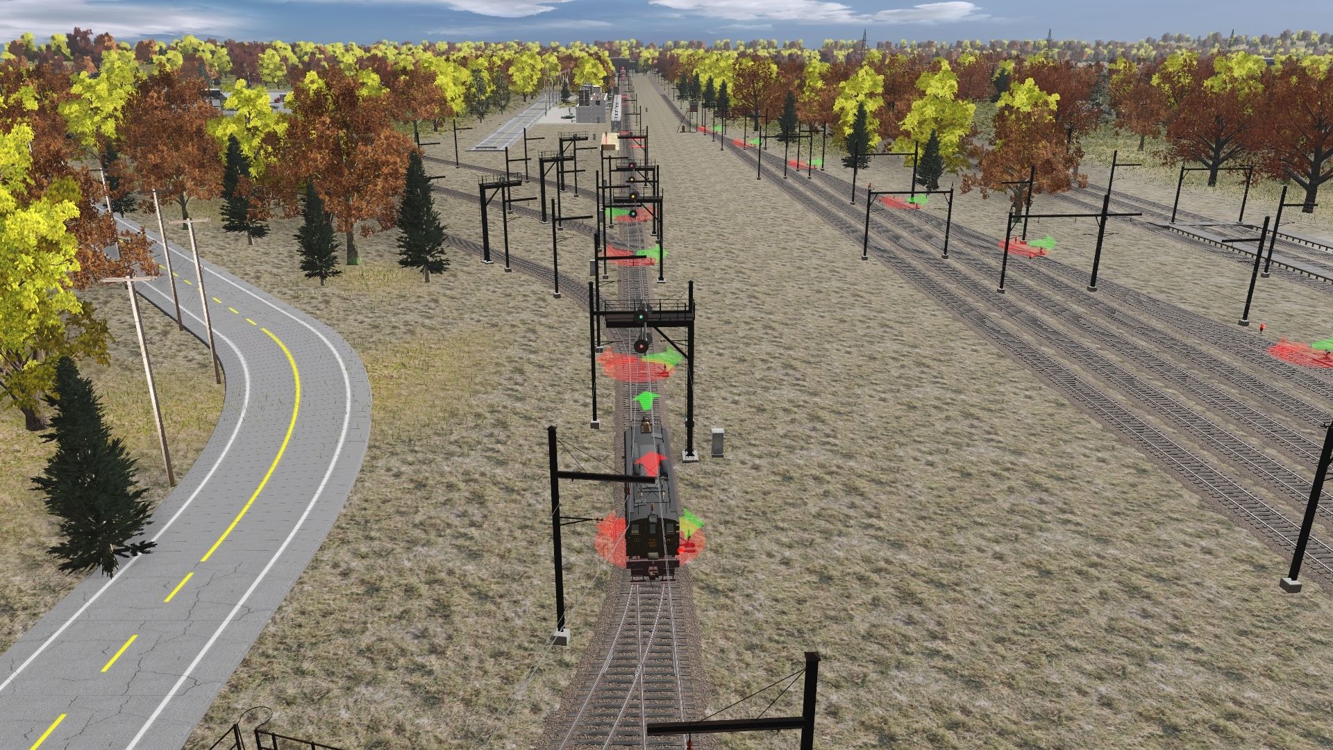
To help you understand, you shouldn't place a signal post in front of every turnout. That's not how it works. The area where all the turnouts are located is called a controlled area. In fact, signal posts are placed to protect this controlled area. They are placed on all tracks entering this area, just before they enter it.
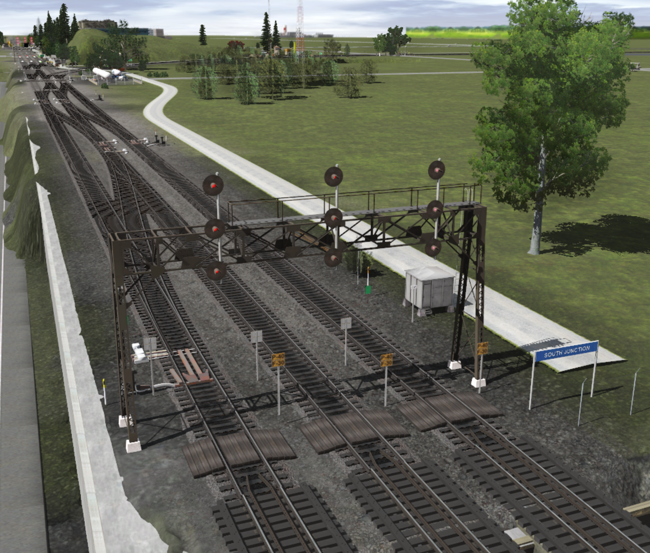
So, one signal post can regulate several diverging tracks within the same controlled area. If there are many turnouts to cross within this controlled zone, offering numerous possible directions and a variety of track types (such as secondary tracks, bypasses, shunting tracks, etc.), there may be one or more turnouts to cross at different speeds. The tracks to which trains must travel also have specific meanings and speeds. You don't travel as fast on a siding as on a secondary track. Therefore, the control zone requires signals with a wide range of direction and speed options. Installing a three-target signal mast becomes necessary, where the third target from the bottom indicates lower speeds.

I know it's very difficult to understand the system until you grasp the concept of the controlled zone. This is fundamental to understanding why there's a mast with one, two, or three targets.

Here's a picture of my layout under construction. (November 2025)


Capture-d-ecran-2025-11-27-104545.png
 
Back
Top