"Scale Modeling" in Surveyor _ Some Observations From a New User

ArthurDaniels

New member
After a hiatus of several years, I have returned to Trainz via Trainz 12. I am a model railroader with an HO 12' by 22' garage layout that will always be a work in progress (trackwork is essentially complete, but little scenery is in place). I am utilizing the "HO Scale" in Surveyor to replicate my layout in Trainz. Thus far, I have completed the trackwork and I am now searching through the Objects and Tracks assets groups to find items such as roads, grade crossings, buildings, etc. of a suitable size to add to my virtual layout. Following are several observations from my efforts thus far:

1. "Scale" track is over sized, whether I am designing in HO Scale or 1:1 Scale. I have checked track gauge by using Rulers to measure track width. Standard American track gauge is 4 feet 8.5 inches. I selected "1 Track US Wood" from the Track list and used the Ruler to measure the gauge on my HO Virtual layout. The Ruler resolves to 0.1 ft increments, so the measurement process is not perfect. However, the gauge of the virtual track measures slightly greater that 0.1 foot, which at a 1:87 up-scaling, would convert to greater than 8.7 Feet. I also selected the same track style in "Real 1:1 Scale" and used the same technique to measure the track width. The result stated on the Ruler is 6.1 feet. So, it appears that track is over-sized in both scales.

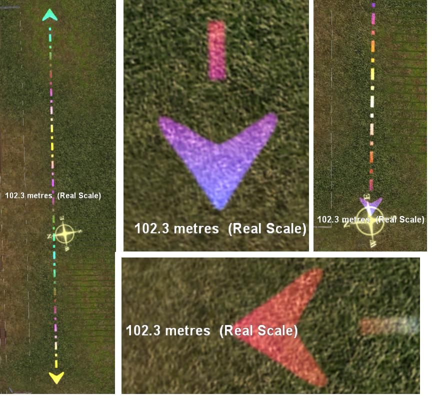
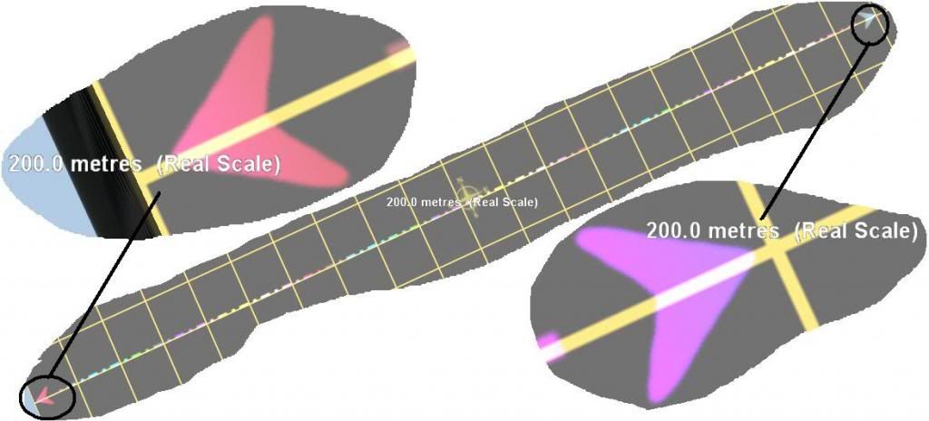
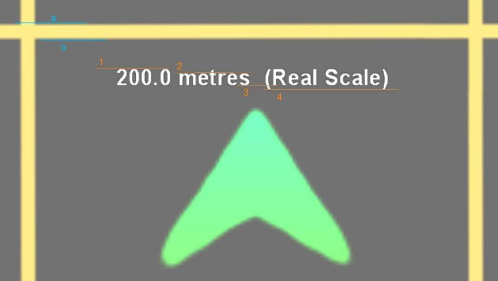
2. When working in HO Scale, I used the Rulers to define the length and width of my overall layout space and to locate certain features, such as curve radii, starting and ending points of various track segments, etc. As an alternative, I set up a new route in Surveyor and used a 1:87 ratio to convert the 22 foot length of my HO layout to 1914 "real-scale" length. I then used the Ruler to plot 1914 feet on the real-scale grid. I expected the actual length on the real-scale version to match the actual length on the HO scale version (as observed by looking at the number of grid sections covered by the two ruler segments). However, to my surprise, I observed that 1914 feet plotted in real scale is considerably longer than 22 feet plotted in HO Scale.

In conclusion, it appears to me that neither scale is accurate in Trainz and that the degree of inaccuracy is not trivial. I am interested in what other people have observed with regard to scale and comments about my measurement process and its accuracy.
 
Last edited:
The Imperial ruler in TRS2006 is flawed, and is inaccurate, however the metric ruler is accurate ... whether they fixed this in higher versions of Trainz IDK

All that is changed in different scales, is the ruler measurement ... loco's railcars, buildings textures, and tracks remain the same size, no matter what scale you use
 
Keep in mind that the Surveyor display is a perspective view and not an "ortho" view. Any precise measurements done with the ruler must be taken from 100% centered on top of the points you are measuring. Also remember that the ruler floats above the ground, so unless you are 100% centered over what you are measuring, this will add to the margin of error. Use your mouse cursor to place the end of your ruler, not the end line or arrow point of the ruler itself.

Using the above mentioned techniques, I just measured the real scale distance between 3 yellow lines in Surveyor and came up with 30.0 meters. I also measured the real scale width between the rails of Auran Track TS2009 Oak and got 4.7 feet, which sounds pretty darn accurate to me.

You might get better precision if you always scale up to real scale since that is Surveyor's native measurement scale. Especially since the ruler can only display 1 decimal position.

Regards,

Andrew

Thanks for your insights. I used your methodology to re-measure both the Auron TS2009 Oak Track and the "1 US Track Wood" pieces, both in Real Scale and HO Scale. In real scale, I was able to duplicate and confirm your measurement of about 4.7 to 4.8 feet gauge, thus confirming the accuracy of the track gauge in real scale. However, in HO scale, the measurement is still off, which I suspect also confirms your comment about track scale and the 0.1 ft increment limitation when working in HO Scale.

I have re-checked my HO Scale and Real-Scale ruler placements, using the close-in, vertical view technique and I can see now that there is close correlation between ruler lengths (as they apply to the grid sections) between the HO Scale and Real Scale ruler lengths for a 2-foot HO segment (176 feet in Real Scale, using a 1:87 conversion - yes, I know that true HO is 1:87.1).

I now realize that I would be better off working in Real Scale, using up-scaling, careful ruler placement and close-in vertical views to replicate my model RR in Trainz. I will re-make my Trainz virtual model, using up-scaling to Real Scale. I will report later on results of this effort and comment upon other aspects as they arise.

One last question about the Ruler: What is the actual end of the ruler? Is it the tip of the arrow, or the line which appears just in front of the arrow tip?
 
Last edited:
Use of the built-in ruler included in the tool flyout can be very frustrating if you desire precise measurements. One of the problems is determining what the end of the measurement is. I've found this varies depending on how close to the baseboard your point of view is. When making this determination you need to be perpendicular to the plane of the baseboard, not the terrain, and, of course, parallax is your enemy. When using imperial measures, accurate for TS12 (and TS2010, as well) but wildly off for TRS2006, as has been mentioned, if you descend as close to the word "Real" at the end, you should find the end point touching the inside of the open parenthesis that surrounds the words (Real Scale).

Personally, I only use the built in ruler for gross measurements. If I really need a precise measurement I use Vulcan's rulers. I like them because they are available both in imperial and robust versions. They are highly accurate when lowered to as close to what you are measuring as possible and include a length of invisible track that allows tacking together multiple rulers to allow measurements of long length. There are a number of other such useful tools by other creators as well. A search for "ruler" on the DLS with all boxes checked should provide a good selection.

Bernie
 
Thanks for the info about alternative Rulers. I am currently using the default rulers to define the edges of the tables which constitute my layout surface. I am using the processes of maintaining perpendicularity and close-in observation to set the rulers. Once I have my layout surface defined and a couple of other mid-line dimensions set, I will no longer need to worry about setting rulers. I have a scale drawing of my layout which I constructed in Excel and this drawing provides the approximate locations of major layout features. I will use this data to recreate these features on the Trainz version of my Model RR. Once I have completed the trackwork in the Real Scale version, I will be able to compare the Real Scale version to the HO scale version in Trainz. I can then report on possible variations, such as track gauge, running time for a train around the layout, etc.
 
Try this

~snip~ One last question about the Ruler: What is the actual end of the ruler? Is it the tip of the arrow, or the line which appears just in front of the arrow tip?
The true point of measurement is not accurately visible from the Surveyor Tool Ruler arrow, or any of its associated displayed text (which will change its position depending on the rotation of your image).

The only accurate pointer is the mouse arrow which will always appear in the centre of the compass. You can use RMB to light up the compass and fine adjust its position. Make sure you are zoomed in and absolutely vertical.

Use the very sharp point of the mouse arrow to place the start point, then drag the ruler to your required finish point using LMB, using RMB at the same time if you want to light up the compass and/or adjust the position on the end point of the ruler whilst still dragging it. Stay close in and vertical and use the mouse arrow point to position the set down point of the ruler end.

Try it across a few 10 metre grid squares and you'll find its accurate.
 
Don't agree

The end of the ruler is the numerals (when viewed at a right angle to the ruler)

Sorry to disagree Cascade, but you’re wrong.

The only way to accurately measure using the Surveyor built in ruler, set to metric, is to use the mouse pointer method outlined in my post #7.

How can the, “end of the numerals”, be a defining point of accuracy when, firstly, the number of numerals will make a difference to the start/end position?

In addition, the “right-angled” position of the numbers will also be different depending on whether you set your right-angle at horizontal or vertical alignment. The compass position will also affect where the numbers are placed. And finally, the zoom position will alter, very considerably, the relative position between the numbers and the arrow point.

Here are a few examples of how those changes show in game. All four shots are viewed from directly above, using the same ruler length. All I've done is to rotate to show the two right-angled positions, and I've zoomed in.

Using the numbers to establish the true start and end point of measurement won’t work.

rulerarrow_zpsd4f7e4a0.jpg~original
 
Measure a grid wthe the ruler, 10m 60, 200m ... You will see that the numerals line up with the grid ... If you adjust the arrows to exactly touch the grid you will be off by 0.50m for every 10m ... so if you measure 200m your way (using the arrow tips) will be off by 1.00m

That equals 39.3701 inches, on this side of the pond, well over a yard, 3 feet !
 
Last edited:
Measure a grid wthe the ruler, 10m 60, 200m ... You will see that the numerals line up with the grid ... If you adjust the arrows to exactly touch the grid you will be off by 0.50m for every 10m ... so if you measure 200m your way (using the arrow tips) will be off by 1.00m

That equals 39.3701 inches, on this side of the pond, well over a yard, 3 feet !
Go back and re-read what I said in post #7.

It’s the mouse arrow that you need to use, not the useless rounded arrow tip of the Surveyor Ruler.

Try it. You might also begin to understand one of the advantages of the “blinding yellow compass”.:D

Here’s your 200 metres. Spot on!!:p

rulerarrow2_zps141514b9.jpg~original
 
casper is right..Real Scale is accurate if you use mouse point..I measured two differant tracks 4.7,4.8..like casper says make sure you are Vertical over object..
 
Being vertical over a grid, and pointing and clicking, dragging the mouse arrow 200 m ... you will see that the ruler numerals are directly on center with the grid (when viewed at 90 degrees to the ruler) ... do I have to provide a screenshot to prove this silly little thing about the ruler
 
Being vertical over a grid, and pointing and clicking, dragging the mouse arrow 200 m ... you will see that the ruler numerals are directly on center with the grid (when viewed at 90 degrees to the ruler) ... do I have to provide a screenshot to prove this silly little thing about the ruler

Yes, pictures are worth 10,000 posts.
 
Being vertical over a grid, and pointing and clicking, dragging the mouse arrow 200 m ... you will see that the ruler numerals are directly on center with the grid (when viewed at 90 degrees to the ruler) ... do I have to provide a screenshot to prove this silly little thing about the ruler
Yes please.

And in case I'm missing something, three questions (also see illustration):

Question 1:
Which part of the numbers/text do you use as the measuring point? Bear in mind that there is upper and lower case and brackets, so you have four possible positions to line up the text with the grid edge.

Question 2:
Which side of the grid line do you place the numbers/text; a or b?

Question 3:
What do you do if there is no adjacent grid line to set your measure against, or the direction angle is not a convenient 90°?

rulerarrow3_zpsbfecde2b.jpg~original


If I wanted to relocate the arrow/ruler ... I would go right overtop, and move the numerals to the next grid line
 
Last edited:
That does seem to work, but only at the 90° angle, with the lower case text exactly overlapping the yellow grid line when zoomed fully in.

It very restricting though. It won't work at other angles and would be impossible when textures have fully obscured the grid. I guess you could then use wire-frame mode, but it's a bit of a faff when the mouse pointer can be seen and used to great effect under any circumstances.
 
Very interesting discussion about the rulers in Surveyor. I am again knee-deep in re-creating my model RR in Surveyor - this time in Real Scale. I am using the Ruler techniques being discussed in this post. Being absolutely vertical and being close-in for final settings and closely-parallel track placements are most important. I am pleased with the results thus far. I have two completed loops now on the virtual model. I plan to run trains at scale speed on both the virtual and real models to compare the results.

However, I can already see that modeling in Real Scale is the only way to have accurate track gauges and roadbed widths, which are vital to being able to experiment with other scenery effects on the virtual model. Up-scaling is simply a matter of using the proper ratio between the scale being modeled and real scale and being patient while developing the virtual railroad.
 
Back
Top