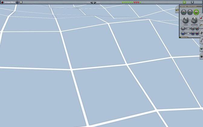
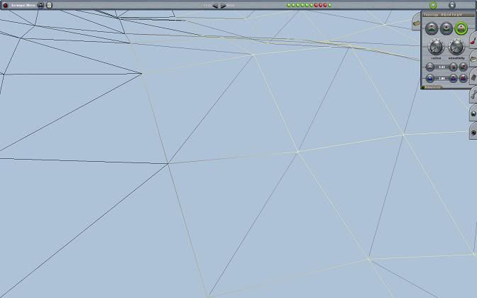
The diagonal Alternative wireframe lines are consistent in that they are all parallel, but only on flat terrain. They change as the terrain is deformed for modelling.
The direction in which the diagonal is placed appears to depend on the height of the adjacent vertices of the 90 deg intersections of the 10m grid.
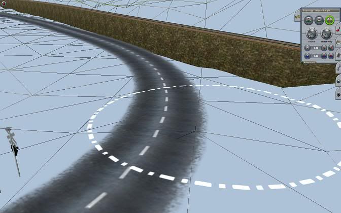
One major advantage of Alt wireframe is that it shows where the baseboard pokes up through laid splines such as roads or tracks. I find this makes it easier to tidy up around these splines.
The diagonals form a hinge along which the polygon will be moved. Being able to see the direction in which that diagonal has been placed within the 10m grid greatly assists that process. It’s a simple matter of grabbing the vertex which sits opposite the hypotenuse and lifting/lowering as required. With practice, this process (at minimum radius) can be further exploited by grabbing elsewhere in the appropriate triangle where the effect is somewhat different. It then affect adjacent grids. This is impossible to explain in text, but trial, error and practice really pays off for all sorts of topology fine tuning.
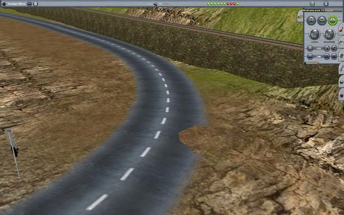
Textured terrain poking through road spline:
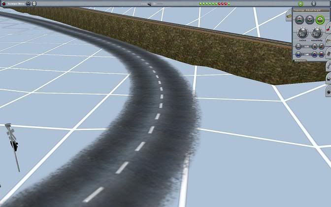
Not visible in normal wire frame:
Visible in Alternative Wireframe:
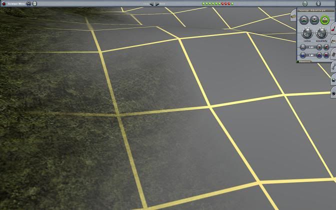
Alt Wireframe also shows where textures have been laid from the Surveyor Paint tools by changing the colour of the frame wires – black for textured, yellow for not yet textured. It even shows the fading between the two.
Part textured and bare baseboard:
Normal wireframe view:
Alt Wireframe showing changes in diagonals and textured/non textured areas:
I’ve seen a theory that Alternative wireframe consumes less resource because it temporarily wipes out all textures. The normal wireframe is, according to the theory, a texture in itself.
Footnote:
Something I’ve not noticed before today is that I
am able to see through the normal wireframe. The revealed parts of the route are not as distinct as in Alternative, but they are faintly visible.
Cheers
Casper