More ladders

martinvk

since 10 Aug 2002
After making a few turnout guides, I realized that I was getting tired of placing several end to end to make simple yards. Getting them all nicely align was a pain.

So, rather than just showing you the end result, I thought I would take on a tour of the whole process.

First, in a CAD program, I laid out the critical dimensions.
2009_yard04cad.jpg

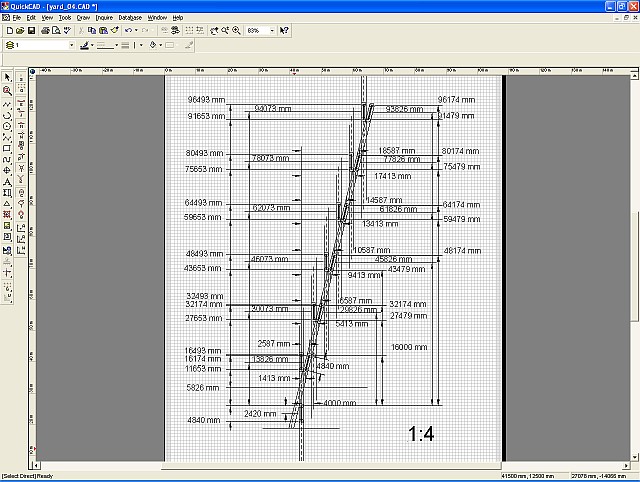
The turnouts are all 1:4, tight but then no one is speeding, right?
The little circles represent endpoints or transitions.

Next in GMax, the CAD design is transformed into a 3D model.
2009_yard04gmax.jpg

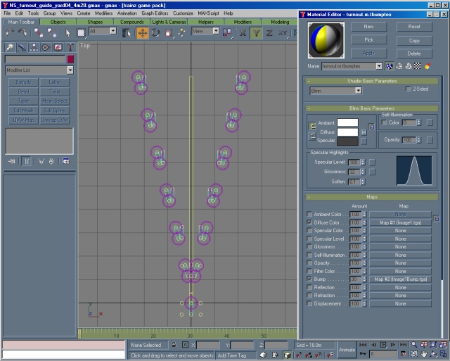
Although not absolutely necessary, the object is TS2009 complaint, using normal maps. Call it part of my learning objects to get used to manipulating normal mapped materials.

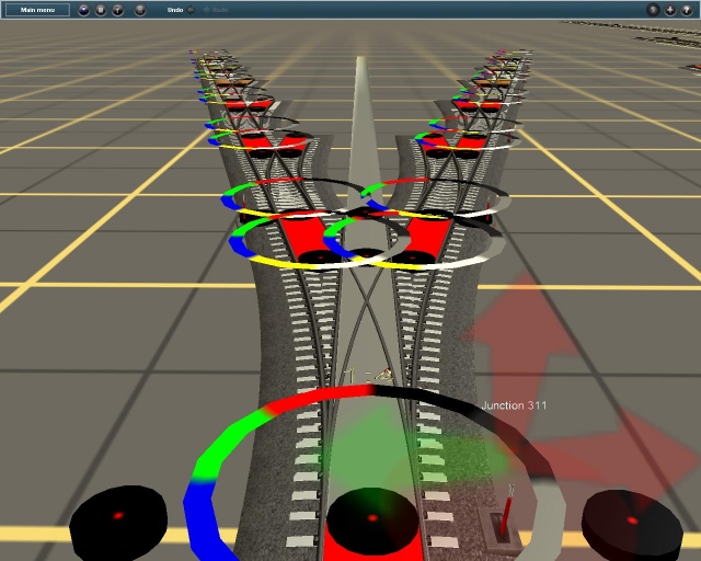
Once it was complete, I imported by dragging and dropping the design folder on to CM2 and presto, it's in TS2009 Surveyor.
Looking from the facing points end.
2009_yard04a.jpg


And a view from the trailing points end
2009_yard04b.jpg


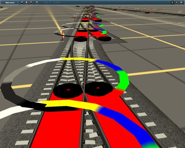
It's just a matter of placing spline joints on each black disk and then using the straighten track tool on the track with the red background. The result is a smooth beginning to a small yard.:cool: The large coloured circles are additional aiming guides built in to the tool. They are the same size as the spline circles.

As you can see, it is not hard to do. Everything from first design through building in GMax to testing in Surveyor was a simple two evening job. :)
 
Yeah....for you maybe! I hope you get alot of satisfaction from your work.
I would not still be doing this for more than six years if I didn't, plus it's so much fun.

I think one of the greatest things that Auran ever did was give us was a place to create and to share our creations. In just about every other game, you only get what the game designers deign to give you. Here, anyone who is willing to try can add to their game environment. Naturally the results can vary from ordinary to extraordinary but even the simplest object is the unique expression of someone's creativity. Thank you Auran.
 
Martin

Most impressive result

I noticed that you had the centre of the circles marked, it would be good if we had a centre mark in the spline circles, this would be more accurate than trying to align to the circle. Working from directly overhead is important when the circles are used for alignment.

A tentative suggestion. Why not make a single thin line alignment track that is used for the initial laying-down and then replace it with the final track for final checking. Would this be easier? Just matter of joining the dots.

What CAD program are you using?

Peter
 
Martin

Most impressive result

I noticed that you had the centre of the circles marked, it would be good if we had a centre mark in the spline circles, this would be more accurate than trying to align to the circle. Working from directly overhead is important when the circles are used for alignment.
Not sure if you noticed but the black disks are in the center of the spline circle guides and the center of the disks have a red dot. When placing track, if I release the track with the cursor exactly on the red dot, then it will be well aligned. The spline circle guides are only secondary guides. As well, the black disks just fit between the rails and so also help with the alignment from any angle. Looking straight down helps but is not required with all the guide features.
A tentative suggestion. Why not make a single thin line alignment track that is used for the initial laying-down and then replace it with the final track for final checking. Would this be easier? Just matter of joining the dots.
Not sure I understand what you mean. In the turnouts, the final track gets placed from disk to disk. Straight over the red background, curved elsewhere. No need for a preliminary track to be placed and then replaced.
What CAD program are you using?

Peter
I use QuickCad from Autodesk. Mine is version 7 build 54 from 1999. An oldie but it still works very well for what I need.
 
Martin

You are correct, the thin line would be no use, I had conveniently forgotten the ugly white band we are afflicted with.

I used a much more simple but similar system on the CTC and found that unless the view was overhead, the vertex circle height above the board caused a parallax error problem. I think that the mouse cursor is not at ground level either.

Peter
 
I use Cadrail 8, a slightly out of date TurboCad 9.5 and an ancient Autocad rel 14 to do my cad work. For track work though I use moslty Cadrail. I have figure libraries for sg trunouts with frog numbers from 4 thru 20 and for ng3 and ng2 turnouts with frogs from 4 thru 12. For custom frogs I have a spread sheet to calc all the dimensions needed to layout the turnout. I do that so the curved leg and straight leg spline points are set so the segments are equal length which ensures the sleepers will line up on the 2 legs and hopefully improve the looks of the spline turnout - which needs all the help it can get.

I had a try at duplicating your yard ladder but couldn't read the pic of the cad work too well so I just used the No 4 sg turnout from my library which has a spacing stub that gives a spread of 12.94 ft (3.95m) between tracks. I think your spacing is 4.0m so I was close. Anyhow the cad work takes maybe 15 min and setting up a kuid/layer definition file and running thru my program another 5 and then 10 min to open TS9 create a new map and edit it in cmp2. About a half hour total.

I like "creative" approaches to solving some of the short comings of Surveyor - even if it took me longer to get it done which often it does. The time I've spent hacking map formats and writing programs I could have finished a few maps but it wouldn't have been as much fun for me. I think you feel the same way about your approach to it.

Bob Pearson


Back
Top