Install the app
How to install the app on iOS
Follow along with the video below to see how to install our site as a web app on your home screen.
Note: This feature may not be available in some browsers.
You are using an out of date browser. It may not display this or other websites correctly.
You should upgrade or use an alternative browser.
You should upgrade or use an alternative browser.
Laying Track?
- Thread starter Alco_P-A
- Start date
")
charwashjohn
New member
Did you do a search on Youtube. I think the general rules apply no matter which TRS you are using. Good Luck!
The actual laying of the track hasn't really changed. You don't have those big circles but that's about the only difference. Where it changes is when you want to edit existing track.
A single click on a section will highlight that section between spline points. You can select one of the end points and move it as before. You can also select the point between the ends and move the whole section as one. Great if it needs to be a bit left or right from where you placed it.
Double click the track and it will highlight between junctions or up to a break in the track that was not intended. A great way to find those gaps. The whole highlighted section can be moved as above.
Approximate spacing can be achieved by eye using the ballast a a gauge or for more precision use one of the many spacing gauges on the DLS. Some are visual only with targets spaced at various distances. Others are objects that the track attaches to enforcing a specific distance between two or more tracks. Once attached you can move the objects around and the attached track will bend and maintain its spacing, up to a point.
Last edited:
The actual laying of the track hasn't really changed. You don't have those big circles but that's about the only difference. Where it changes is when you want to edit existing track. A single click on a section will highlight that section between spline points. You can select on of the end points and move it as before. You can also select the point between the ends and move the whole section as one. Great if it needs to be a bit left or right from where you placed it. Double click the track and it will highlight between junctions or up to a break in the track that was not intended. A great way to find those gaps. The whole highlighted section can be moved as above. Approximate spacing can be achieved by eye using the ballast a a gauge or for more precision use one of the many spacing gauges on the DLS. Some are visual only with targets spaced at various distances. Others are objects that the track attaches to enforcing a specific distance between two or more tracks. Once attached you can move the objects around and the attached track will bend and maintain its spacing, up to a point.
The actual laying of the track hasn't really changed. You don't have those big circles but that's about the only difference. Where it changes is when you want to edit existing track. A single click on a section will highlight that section between spline points. You can select on of the end points and move it as before. You can also select the point between the ends and move the whole section as one. Great if it needs to be a bit left or right from where you placed it. Double click the track and it will highlight between junctions or up to a break in the track that was not intended. A great way to find those gaps. The whole highlighted section can be moved as above. Approximate spacing can be achieved by eye using the ballast a a gauge or for more precision use one of the many spacing gauges on the DLS. Some are visual only with targets spaced at various distances. Others are objects that the track attaches to enforcing a specific distance between two or more tracks. Once attached you can move the objects around and the attached track will bend and maintain its spacing, up to a point.
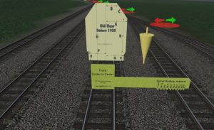
I just uploaded to the DL station 4 clearance gauges: Before 1920, Classic, Early Modern and Modern. They all start with "Clearance Gauge". The dimensions of these gauges taken from the NMRA Recommended Practices, RP-7.1. The RP-7 series is a comprehensive discussion of clearances throughout the history of US railroads. The cone is center-to-center distances between two parallel tracks. Please realize this c-c distance increases for curves.
Any comments of these gauges will be appreciated.
Any comments of these gauges will be appreciated.
While waiting for them to be approved and for them to show up in the DLS, I would like to suggest also having a look at the "Guide"series I made back in the day for TRS2004. A bit long in the tooth but still functional. Guide 2t 3.5m, Guide 2t 4m, Guide 2t 5m, etc. 2t is how many tracks can be attached, it ranges from 2t to 5t. The 3.5m is the C-C distance between the tracks and ranges from 3.5m, 4m to 5m. Your track attaches and replaces the invisible (red) track that is a place holder. The push pin is a Surveyor only piece that helps find them once they are placed.
Please realize the Clearance Gauge tools I have uploaded to the DL station contain a track c-c for tangent yard tracks only. In order to handle c-c spacing for track outside of the yard NMRA RP-7.2 provides information. For instance, for Tangent track the following is offered:
Old Time/Narrow Gauge (pre-1920): 12 feet
Classic (1920-1969): 13 feet
Early Modern/Modern (after 1969): 14 feet
For curves, this becomes more complicated. NMRA RP-7.2 provides the following information:
It would be nice to have a tool that uses this information and that could be used in Trainz
Old Time/Narrow Gauge (pre-1920): 12 feet
Classic (1920-1969): 13 feet
Early Modern/Modern (after 1969): 14 feet
For curves, this becomes more complicated. NMRA RP-7.2 provides the following information:
| Curvature (degrees) | 0 | 5 | 10 | 15 | 20 | 25 | 30 | 35 | 40 | 45 |
| PROTOTYPE Radius(ft.) | Tangent | 1146 | 574 | 383 | 288 | 231 | 193 | 166 | 146 | 131 |
| Old-Time/NG (ft.) | 12.0 | 12.7 | 13.4 | 14.0 | 14.7 | 15.3 | 15.9 | 16.5 | 17.0 | 17.5 |
| Classic (ft.) | 13.0 | 14.2 | 15.5 | 16.7 | 17.8 | 18.9 | 20.0 | 21.0 | 22.0 | 13.0 |
| Early Modern/Modern (ft.) | 14.0 | 15.0 | 15.9 | 16.8 | 17.7 | 18.6 | 19.4 | 20.2 | 20.9 | 21.6 |
| Reference: NMRA RP-7.2 |
It would be nice to have a tool that uses this information and that could be used in Trainz
There is a mistake in the table above. Classic(ft.), 45 degrees Curvature shows 13.0 ft. This should be 23.0 ft.
I have converted feet to meters as shown in the table below.
I have converted feet to meters as shown in the table below.
| Curvature (degrees) | 0 | 5 | 10 | 15 | 20 | 25 | 30 | 35 | 40 | 45 |
| PROTOTYPE Radius(meters) | Tangent | 349.3 | 175.0 | 116.7 | 87.8 | 70.4 | 58.8 | 50.6 | 44.5 | 39.9 |
| Old-Time/NG (m) | 3.7 | 3.9 | 4.1 | 4.3 | 4.5 | 4.7 | 4.8 | 5.0 | 5.2 | 5.3 |
| Classic (m) | 4.0 | 4.3 | 4.7 | 5.1 | 5.4 | 5.8 | 6.1 | 6.4 | 6.7 | 7.0 |
| Early Modern/Modern (m) | 4.3 | 4.6 | 4.8 | 5.1 | 5.4 | 5.7 | 5.9 | 6.2 | 6.4 | 6.6 |
| Reference: NMRA RP-7.2 |
Last edited:
Once again, I made a mistake in the last table. Change Prototype Radius 15 degrees from 175.0 to 116.7. Changed.
I have designed a tool based on this information for Old Time, pre 1920. I will post a picture as soon as I figure out how to post a picture.
Well, I can't figure it out. The tool looks like a key with notches at each of the 10 distances shown in the table above.
I have designed a tool based on this information for Old Time, pre 1920. I will post a picture as soon as I figure out how to post a picture.
Well, I can't figure it out. The tool looks like a key with notches at each of the 10 distances shown in the table above.
Last edited:
You don't post a picture directly. Save it on a publicly facing web page. Then link to that location by clicking on the Insert Image icon above or Ctrl+P to open the dialog box. Type or paste the complete address of the image.
Some of my guides in Classic Surveyor

Some of my guides in Classic Surveyor
Last edited:
I successfully uploaded my screenshot to the Trainz Portal; copied the url and tried to post it here. I clicked on the "Insert image" and pasted the link into the box provided. It does not work.
Here is the link: www.trainzportal.com/mytrainz/view_media_post?media_post_id=510322. What did I do wrong?
Here is the link: www.trainzportal.com/mytrainz/view_media_post?media_post_id=510322. What did I do wrong?
Last edited:
When I click on the link, I see the image in a new window, so that works. I've not used the Trainz Portal for images so not sure if that is the only way to use it.
Here is how I used Davoss's gauge. The measuring stick behind his gauge is mine showing the c-c distance at 4.1m.

Here is how I used Davoss's gauge. The measuring stick behind his gauge is mine showing the c-c distance at 4.1m.
Like this

I don't know what you did differently but these were my steps
I don't know what you did differently but these were my steps
- Right click on the image in the Trainz Gallery and select the option Copy Image Link
- Open your forum post, click the Insert Image icon
- Paste your copied link (step 1 above) into the URL box
- Click the Insert button
I think you have to put that link into the dialog box when you click Ctrl+PWhat did I do wrong?
Pware got there before me.
Similar threads
- Replies
- 11
- Views
- 625