Railwoodman
Well-known member
Wow ............yea and Wow .. that's nice .
Matt
Matt
Follow along with the video below to see how to install our site as a web app on your home screen.
Note: This feature may not be available in some browsers.
Piere,
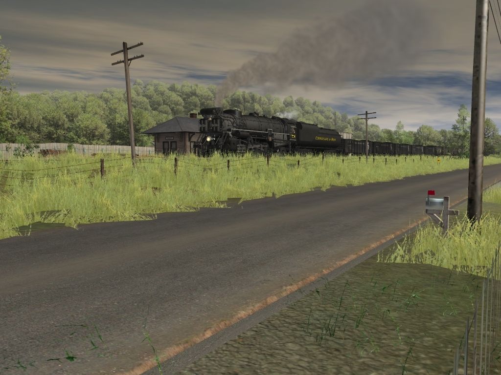
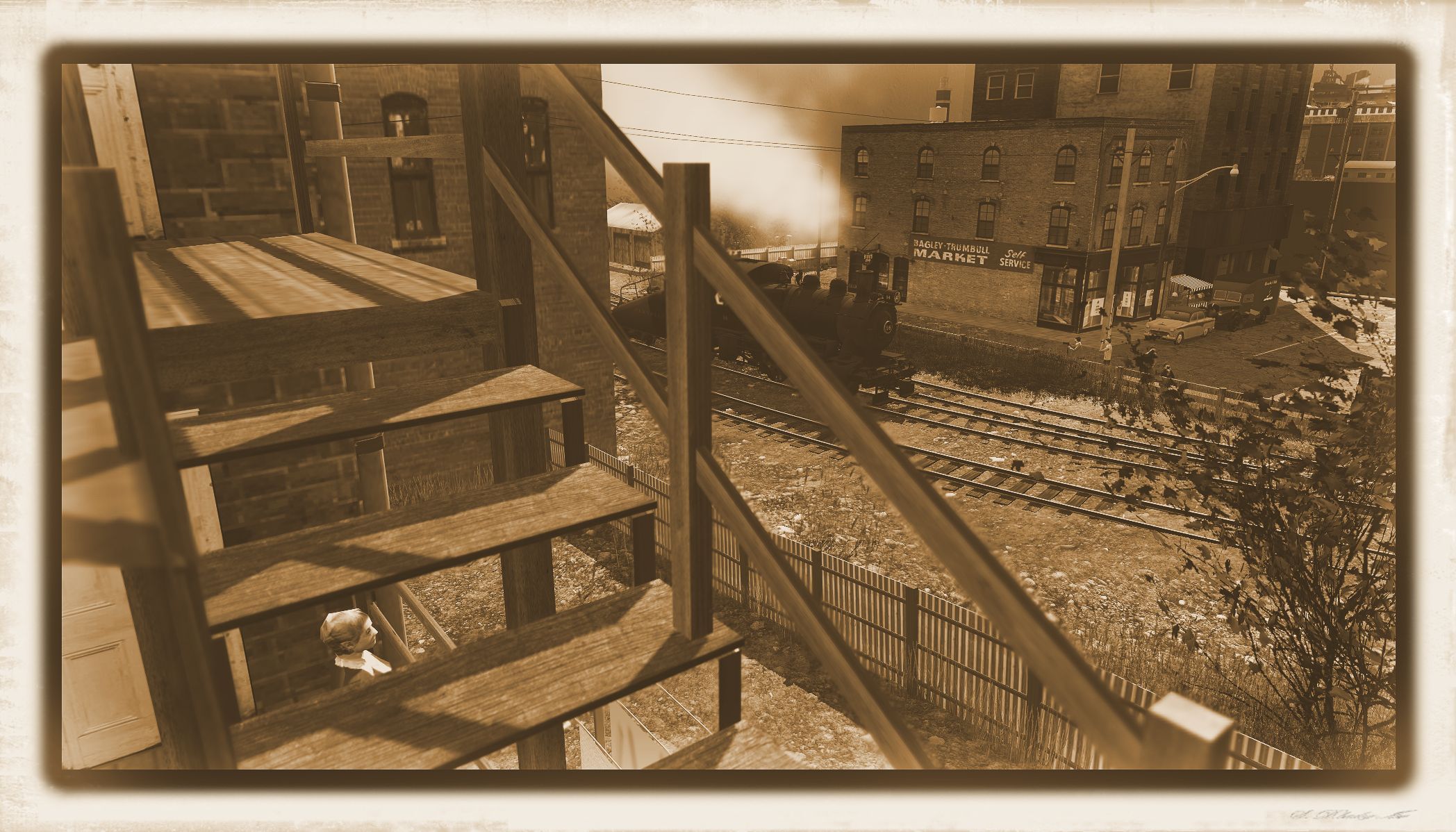
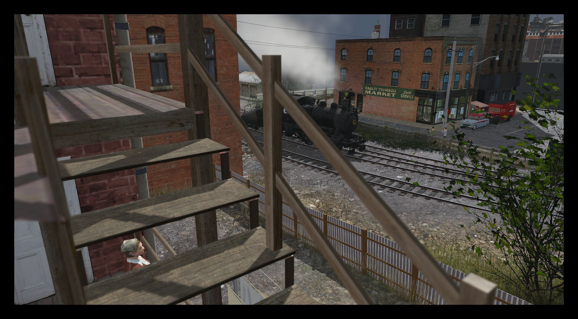
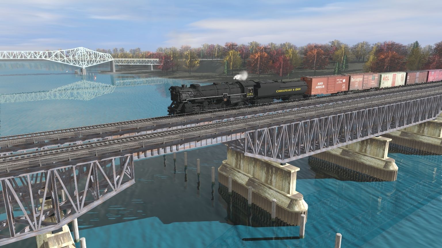
These shots are amazing! The East Harbor one, shown from the reverse angle of the one you posted of the ship in a different thread, has the look of a painting - it is so well composed. :Y:
Beautiful job!
Heinrich505
Wow ............yea and Wow .. that's nice .
Matt
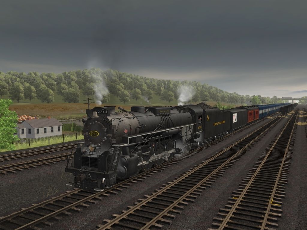
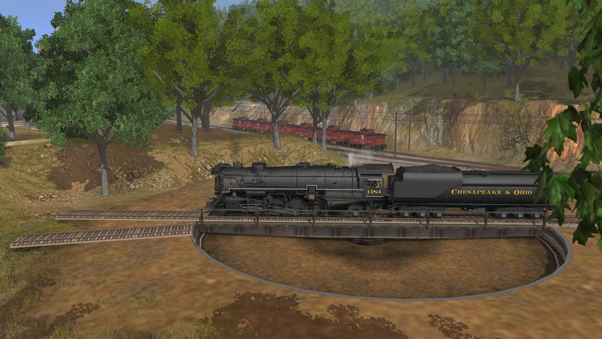
As a person from overseas can I ask question? I assume that's a feedwater heater on the front end. But also two cross compound air compressors? And another air compressor on the left side? What were these locomotives used for? Extremely heavy trains on steep downgrades where air braking ability was essential?
Phil
I believe that one on the side is part of the feedwater heater and yes the tank in the front is part of the feedwater heating system. I think it is an Elesco type system.As a person from overseas can I ask question? I assume that's a feedwater heater on the front end. But also two cross compound air compressors? And another air compressor on the left side? What were these locomotives used for? Extremely heavy trains on steep downgrades where air braking ability was essential?
Phil
Yes, two compound air compressors. It's fairly standard on larger engines (see Timken 1111, the SP 4-8-4s and 2-10-2s, UP MT-73, and every 4-10-2 built in the US for further examples), as a single compressor is rated for 150 CFM and most road-length trains need considerably more to sustain a partial application safely. As Ken pointed out, the pump mounted on the side is not a third pump; rather, it is the water pump for the ELESCo feedwater system. Note how it does not have the same asymmetrical cross-compound design as the pumps on the front, and has a patent plate covering the water cylinders. These are the easiest identifiers for such a part. That pump draws water directly from the tender, and pushes it through the feedwater bundle, which is essentially an array of radiator pipes surrounded by exhaust steam from the power reverser, air compressors, water pump, steam heat if fitted, and so on. Once the water is heated, it feeds directly into the boiler, while the exhaust steam, now cooled to the point of condensation, is funneled back into the tender to be re-used.As a person from overseas can I ask question? I assume that's a feedwater heater on the front end. But also two cross compound air compressors? And another air compressor on the left side? What were these locomotives used for? Extremely heavy trains on steep downgrades where air braking ability was essential?
Phil