Gradient Problem

BuilderBob

New member
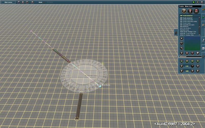
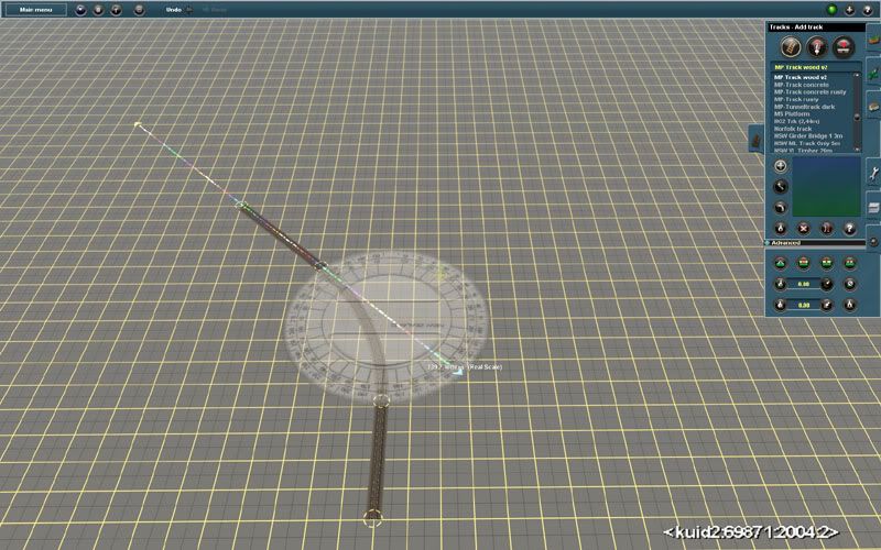
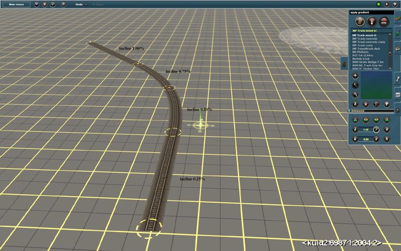
I am creating a mountain section of track and have carefully set the gradient between spline points at exactly 2. I have adjusted the size of the loops, where necessary, to get the required height change while maintaining a gradient of 2.

But when I run a train along the track and watch the HUD the gradient between the splines actually varies from 0.40% to over 5%! - it isn't the steady 2 that the gradient tool was telling me. Perhaps it's 2 on average, but I want it to be consistent over the whole length. It seems to flatten out where the line is straight and steepen up where line curves. Or, perhaps, it's flatter where it runs perpendicular to the line between the spline points, and steeper where it's parallel to that line.

The sections before and after the problem one also vary, but not so wildly. They are both a nominal 2, so there should be minimal problems resulting from any smoothing of the gradient change between sections.

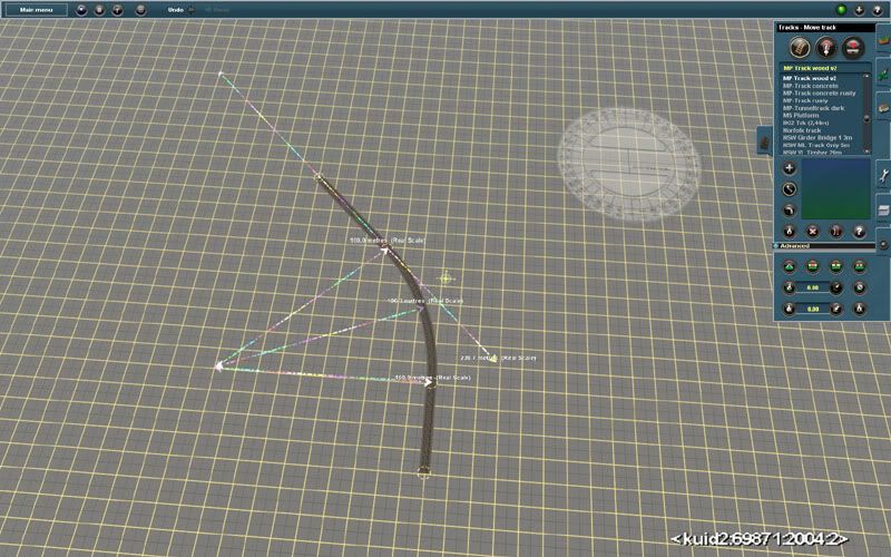
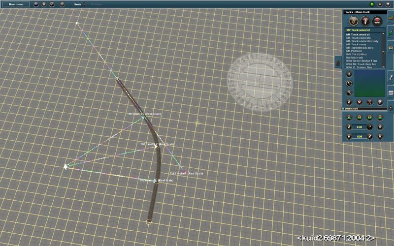
I assume that if I insert extra spline points I will get more precise control over the gradient in each section, but that destroys the smooth sweeping curves that the long sections generate - I can't find a way to simply insert extra splines without disturbing the existing layout and creating extra reverse curves that i don't want.

Is there anything I can do to force a more consistent gradient between spline points, or to insert extra spline points without changing the layout?
 
First question I would ask is - is the distance between the spline points the same or does it vary from point to point? Reason I ask is I think Ive read somewhere that it has a baring on the gradient. Im sure someone somewhere will correct me if Im incorrect.
 
As I understand it, it is a matter of angles and vectors. If you have two spline points, say 200M apart, and you use the gradient tool to set it to 2% it will read 2%. Leaving the gradient tool set to 2% and then - one by one - touching the tool to each spline point all the way up the grade you will see 2% everywhere. That is IF the splines are all 200M apart.

Now, If you lay track and the spline points happen to be something different than 200M apart (for example, remember) then the same 2% will either create a steeper or shallower grade dependent on how much further (or closer) the spline points are. If the splines are 100M apart, then the 2% has to climb faster to reach the next spline; if the spline is further than 200M, then the grade can relax and the 2% is spread out more.

I ran into this at every spot when I created the grades for the DHR. I ended up running 2 or 3 KM at a given percentage (with no regard to how far apart the spline points were) and then went back over it adjusting grades until I could click "get gradient" and any point and find it was consistent. It is a ticklish job and very tedious, but very rewarding when you see the overall result.

Bill
 
Bill: Thank you for your explanation..It never entered my mind..It sure makes sense..Because in the real 2% would be 2FT rise for every 100FT forward..
 
If you lay multiple lengths of track, of various lengths, all connected in a either a straight line or a curve, and set each segment at 2%, all of the lengths will show a 2% gradient regardless of their developed length.

The only difference will be the elevation at each spline circle, which is proportional to the length of the segment.

Now, if you go back to the beginning of the track and reduce one of the gradients to say, 1%, the gradient of the next segment will increase in proportion to its length. This is what Bill was talking about.

If you change a segment gradient, whether higher or lower, only the elevation at the next spline circle will change. All of the remaining elevations beyond that point will remain the same.

If you build enough routes, one problem that you'll find is a missed gradient. You've set all of your gradients, brought the terrain up to grade, and everything looks great. Now you start double checking your grades only to find that one of them is 12%, which means that you missed a gradient. Now you have to start all over and redo the whole process

One thing to keep in mind is where you click on the track to set the gradient. If you click beyond the halfway point of a length of track, You'll get the gradient in the opposite direction. This can throw everything off.

Joe
 
Joe is absolutely right. That was what I was trying to get across. In the construction of the DHR there were times I was ready to throw my hands up in the air. One particular spot I had to re-do around 10 times because I kept missing at least one segment. If you are doing a long climb (as in the DHR where we went from 500 feet to over 7400 feet) it is handy to use contour markings as a guide.

By that, I mean before you try laying track, you use the water level method to locate lines of same contour and use a contrasting color texture (one you can erase alter) to mark them. Using these lines, you can measure out your climb with a calculator. For example, you want to go from 3500 feet to 4000 beet and you only have 10 miles to do it in. This way, you can put in enough curves and such to make the gradient as gentle as you can for the distance covered.

Bill
 
Sounds good but that's not quite the way it works. Gradient is the height difference between the 2 spline points divided by the arclength of the track's projection in the horizontal plane. It's simple geometry. If the projected length is longer or shorter the height difference applied by the tool when setting the grade changes in direct proportion.

When working with the slope of the Trainz track spline it's a bit more complicated. The track spline is a true 3d spline and curves in both horizontal and vertical planes. Surveyor's gradient tool works only with the height difference and projected arc length. In Driver the HUD display shows the actual slope of the track spline in the vertical plane directly below the locomotive. The 2 are not usually the same unless you take a lot of care to enforce end tangents in the vertical plane with selective use of the straighten tool. And nobody that I'm aware of does that. For horizontal curves some people do but not vertical.

Every change in grade will introduce a curve in the vertical plane of track spline that propagates into the adjacent sections. The height of the spline points still gives the geometrical gradient that was set but the spline doesn't follow a straight line between the points - it curves in both horizontal and vertical planes. The variation from the constant grade that's set in Surveyor can be quite large. Also moving a spline point even just a bit after the grade's been set will change the grade and also introduce more vertical curves in the adjacent sections of the track spline.

Bob Pearson
 
Bob and Joe have it - the grade set in 'apply grade' is if you like an 'average' over that length of track, but the actual grade at any point along the track will vary. If you change from 'level' track to say 1% grade, the change is not instantaneous at the spline point, but is a gradual vertical curve over the two adjoining track lengths. The HUD shows the instantaneous grade at that exact point in the track which will vary as the vertical easement is traversed. If you set up a test in surveyor and set one length of track as level and then lay an extreme grade - say 5% - off it you can see the curve. In fact if you straighten the 5% segment the adjoining 'level' track will adopt a pronounced 'U' shape diving below the base board. It will still show as 0% though because the two ends of the 'U' are at the same level. This is extreme, but the principle applies on all grades...

Andy
 
Sounds good but that's not quite the way it works. Gradient is the height difference between the 2 spline points divided by the arclength of the track's projection in the horizontal plane. It's simple geometry. If the projected length is longer or shorter the height difference applied by the tool when setting the grade changes in direct proportion.
That the gradient might be calculated over a linear distance was my first concern, but that was easily dismissed. That the arc distance calculation might be inaccurate did occur to me, but I was not originally concerned with the actual path length calculation - I just needed it to be long enough to get the required height change at the given (average) gradient - the exact length needed to achieve that didn't matter. That approach also means that any need to project the track onto the horizontal plane to calculate distance would not affect things.

When working with the slope of the Trainz track spline it's a bit more complicated. The track spline is a true 3d spline and curves in both horizontal and vertical planes. Surveyor's gradient tool works only with the height difference and projected arc length. In Driver the HUD display shows the actual slope of the track spline in the vertical plane directly below the locomotive. The 2 are not usually the same unless you take a lot of care to enforce end tangents in the vertical plane with selective use of the straighten tool. And nobody that I'm aware of does that. For horizontal curves some people do but not vertical.
I will try enforcing end tangents by using straight sections before and after, but adding sections, especially straight ones, is what I am trying to avoid. As noted in the original post, the before and after sections in the problem case also have an average of 2%, so I would have thought vertical smoothing issues would be minimal. I can see that variation odccurring in other sections, but nothing as extreme as this particular one. I will try to use the HUD to create an elevation map of all three sections, to gauge what impact the vertical smoothing might be having. That might also help with my theory that the slope is somehow related to the curvature.

Every change in grade will introduce a curve in the vertical plane of track spline that propagates into the adjacent sections. The height of the spline points still gives the geometrical gradient that was set but the spline doesn't follow a straight line between the points - it curves in both horizontal and vertical planes. The variation from the constant grade that's set in Surveyor can be quite large. Also moving a spline point even just a bit after the grade's been set will change the grade and also introduce more vertical curves in the adjacent sections of the track spline.

So experimenting with small movements of the spline point is possible, but probably not practical without some other means of getting point gradient than using the HUD in Driver. The other option is smaller sections and more direct control of the local gradient.

Which leads me to my second question - is there some way to insert extra spline points without disturbing the current path - the extra points turn the existing sweeping curves into wiggles that are extremely difficult to remove. I will end up with many more points than I want, each one needing to be height adjusted to get the required gradient!
 
If you lay multiple lengths of track, of various lengths, all connected in a either a straight line or a curve, and set each segment at 2%, all of the lengths will show a 2% gradient regardless of their developed length.

The only difference will be the elevation at each spline circle, which is proportional to the length of the segment.

Now, if you go back to the beginning of the track and reduce one of the gradients to say, 1%, the gradient of the next segment will increase in proportion to its length. This is what Bill was talking about.

If you change a segment gradient, whether higher or lower, only the elevation at the next spline circle will change. All of the remaining elevations beyond that point will remain the same.

If you build enough routes, one problem that you'll find is a missed gradient. You've set all of your gradients, brought the terrain up to grade, and everything looks great. Now you start double checking your grades only to find that one of them is 12%, which means that you missed a gradient. Now you have to start all over and redo the whole process

One thing to keep in mind is where you click on the track to set the gradient. If you click beyond the halfway point of a length of track, You'll get the gradient in the opposite direction. This can throw everything off.

Joe

All this is quite correct, but not relevant to my problem. The point I was making was that, after doing all that and getting the grade to a steady 2% along at least 3 sections (it's actually more like 6), the variation in gradient at a particular point within a middle section seems to be out of all proportion to any residual height smoothing effect that could be created by adjacent sections.

I could get finer control of the gradients within that section by adding more spline points, but how do I do that without turnng the smooth curves of that section into a series of reverse curves?
 
I could get finer control of the gradients within that section by adding more spline points, but how do I do that without turnng the smooth curves of that section into a series of reverse curves?

I don't think you can. The 'Apply Grade' tool is setting an 'approximate' or 'average' grade, not an absolute. On a straight track it will work out pretty good, specially in a track segment wich isn't at the 'end' of a grade. On a curve though there are going to be variations, there have to be variations. Where is the grade calculated? Inside rail, outside rail, centerline? The absolute grade on all three will be different in a curve, the outside rail is longer but gains the same vertical change as the inner rail, which is shorter and therefore less 'steep'. You would even need to know if the HUD reads from the same palce as the Grade Tool applies the grade!

Bear in mind that all this appies to the prototype as well - a grade signposted as 2% is the average grade: it will be close to 'exact' but won't be perfect. From a broad perspective, in Trainz does a small variations in the 'posted' and 'actual' grade matter? I'd put the smoothness of the curve way ahead of the 'exactness' of the grade...

Andy :)
 
Last edited:
When laying curves, each curve should have an odd number of spline points between two straightened sections. For a simple 90 degree curve I usually use three equally spaced spline points, except if it is in a yard where I only use one. If it is a really long curve, like a horseshoe curve I would use either five or seven spline points depending on the radius. If you curve has a straightened section at each end you can add spline points without distorting the track by inserting the first one in the centre of the curve then divide the two halves again the divide these four sections equally again. This will give eight sections of equal length to which you can apply a steady gradient.

Just my method.

Bill69
 
...
Bear in mind that all this appies to the prototype as well - a grade signposted as 2% is the average grade: it will be close to 'exact' but won't be perfect. From a broad perspective, in Trainz does a small variations in the 'posted' and 'actual' grade matter? I'd put the smoothness of the curve way ahead of the 'exactness' of the grade...

Andy :)

It wouldn't matter in the slightest if it was a small variation, but it isn't. The example I'm using varies from 0.21 to 7.65 for a nominal grade of 2. I would like to put the smoothness of the curve ahead of the grade variations, but that sort of variations looks ridiculous.
 
This is the height map. As you can see, the variations are extreme, and do not seem to be related to any problem smoothing the 2% into the start and end - in fact, the top section where it flattens is quite well smoothed. The bottom portion is a 2% straight through a tunnel and that also smooths into the first section quite well. Perhaps I need more tunnels and bridges. A B C D E F are the spline points, and the numbers next to them are the gradient in that direction.

The map makes it clear that the problem is associated with the spline points, but since the spline points also define the horizontal curvature then that probably doesn't help much.
 
What does the gradient tool actually do? As I understand it, the exact curve of a spline is defined by its end points and the next endpoints at either end (assuming no straightening). Does the gradient tool adjust the height of any of those four points, or does it actually prescibe the gradient through that spline point?

Also, how does it decide if which direction is up?

Personally, I prefer to set the height of each spline point, estimating how much the height has to rise by at each spline given its distance from the start of the slope, and typing the number in the box.
 
@ Bob - do you have fixed or floating (yellow or white) track vertexes?

@F2A - The tool applies a selected grade to a specific length of track. The gradient can be specified as positive (up) or negative (down). The "Apply grade" tool is used by clicking once on each track segment close to (but outside) each spline point.

I use only the 'Apply Grade' tool on all my routes. I get some variation in grade, but nothing like the variation described by Bob, which is what makes me think there is something else going awry...
 
So long as you set the height of the FIRST spline point, when you use the apply gradient tool the next spline point will be fixed and you sould not have to change it's height.

Here is an example of how I do curves and inclines.

If it is a prototypical route I use the protractor to get the angle right, if it is a freelance route I sometimes don't bother with the protractor but I have included it here for clarity.

First lay the two straight sections and use the straighten tool on them

curve-1.jpg


Next joint the two straight sections with a contiuous section of track

curve-2.jpg


Next measure the radius and bysect the angle with a third ruler the same length or slightly longer.


curve-3.jpg


Place a spline point where the third ruler meets the track and drag it outward to the end of the ruler, so the arrow is in the middle of the track.
curve-4.jpg


That completes the curve. If it is a very tight curve the centre spline point can be draged out a bit more and the spline point at each end of the curve can be moved away from the centre of the curve.
This gives a more gradual transition from straight to curve.

incline-1.jpg


Now the incline. There are four sections to this piece of track, starting at the bottom of the pic the first section incline is 0.25%
Next section incline is at 0.50%. Third section is at 0.75% and the fourth section is at 1.00%
When you get to your required incline using small steps like this just keep adding track at the same incline.

NOTE: you can save these pics to your desktop then enlarge them with a photo editing program for more clarity.

Hope this helps someone to lay nice smooth track.

Cheers,
Bill69
 
Last edited:
What does the gradient tool actually do? As I understand it, the exact curve of a spline is defined by its end points and the next endpoints at either end (assuming no straightening). Does the gradient tool adjust the height of any of those four points, or does it actually prescibe the gradient through that spline point?

Also, how does it decide if which direction is up?

Personally, I prefer to set the height of each spline point, estimating how much the height has to rise by at each spline given its distance from the start of the slope, and typing the number in the box.

When you click the tool on a section of track, there will be a near spline point and a far spline piont, calculated form the click position. The far spline point has its height changed so that the average grade from the near point (not the click point) to the far point is as per the gradient setting. If this value is positive, the far point will be higher than the near point. If it's negative, the far point will be below the near point. The height of the far spline point is calculated using the track length. The result should be a section of track that has the nominated gradient for it's whole length, even if curved. In practice, the gradient of adjacent sections will affect the gradient of the selected section for some (unspecified) distance into its length. If the track is already laid beyond the far spline point then the gradient of the following section will be changed, and the two sections will affect each other's local gradient in the vicinity of the far spline point.

If the following track section is then set to the same gradient, then its far spline point height will be adjusted, and (I expected) that subsequent sections with the same gradient would have a constant gradient along their length. That's what is not happening.
 
@ Bob - do you have fixed or floating (yellow or white) track vertexes?

All the vertices have their yellow circles. I can change the gradient for any section and the far spline point moves as I would expect, and the next section has its nominal gradient adjusted in proportion to their repective lengths. Then I change it back to 2 and everything goes back to exactly how it was.
 
Back
Top