Are your DEM gradients wooping you ... Take back control !

cascaderailroad

New member
Use multitrack to keep the track spacing at 4m ( I use MB Finescale Quad 4m )

Trace all your DEM straights, and extend straight track so that they intersect out beyond the curves

Measure back from the intersection, using the Trainz ruler, two equal distances, and apply track spline point circles at those 2 locations

Connect curve sections to the multitrack straight track

In curves you may have to apply guess-timate intermediate spline point circles, to smooth out the curve so that it is not warped, and so that it is a symmetrical curve.

You can measure curve radius using the mysterious "Get Curve Radius" button, by just touching the very outside edges of both sides of the spline point circle (NOT the center of the circle) !
Screen_001_zpszl203dnw.jpg


Using the Google Earth Ruler / Line / Path / Metric (you can set it so that it shows everything in metric)

Draw long lines so that they intersect, and only trace the straight track paths
Mapleton_zps9qkehqao.jpg


Trace your entire route, only the straight track sections, from end to end
Petersburg%20to%20Enola_zpskrcnwwtm.jpg


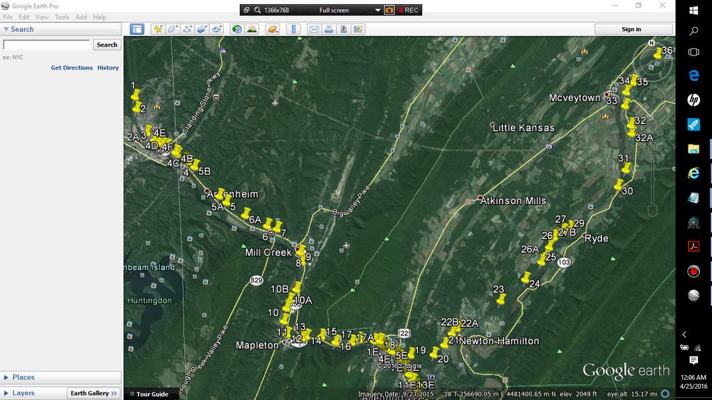
Place pushpins at every end of a straight track, and in the middle of curves, and zoom in all the way ... place the GE hand on the track, and note the metric height reading on the lower right ... re-name all the pushpins the respective heights, all along your route.

Save this path in your Google Earth temporary file, by hitting the save button, as well as save when closing Google Earth, then it will be there many months, or years from now, for you to use
Pushpins_zps6cbffo2g.jpg


Type in these pushpin track heights in Trainz Surveyor, and apply them to each respective track spline point circle.

You will have to run Trainz windowed, so that you can view 2 windows (Google Earth, and Trainz together)

On the PRR Middle Division, the average gradient is @ 0.10%, and rarely exceeds 0.20% ... so if one gradient measures 0.30%, and the next one measures 0.10%, you may have to fine tune the two conflicting gradients to be equal at 0.20%

If one end of a curve is 119m track spline point height, and the other end of the curve is 118m track spline point height ... the center curve spline points will be split between those numerals at 118.5m track spline point height

After many, many months, after you have all the gradients and curves are all fine tuned, you can swap out all the multitrack with single track, and then use the "Smooth Spline" tool button ... I repeat: "After Many, Many months of fine tuning" ! Do not be in a rush to deform your DEM with the Smooth Spline tool !
 
Last edited:
Great.....now I am going to have to try this. LoL

I've just sort of eyeballed it most of the time but I'll test this out.
 
You know you can import the route layer available on the Geologic Survey server if the route exists?

This will produce a Google Earth KML file which can be imported into TransDEM.

John
 
I see there has been 131 views and no one has thanked you for the input, that can be helpful to many, so I will say thank you for the input.
 
... so I will say thank you for the input.

I agree - thanks Cascaderailroad. I have only just started using TransDEM after owning it for several years now and I am still trying to figure things out. This will be of considerable help.
 
I tried a different but similar technique . And still had big issues with grades . My opinion is that some DEM's aren't vary accurate to some of the elevation . I base this on the data and grades I personally know and have modeled in HO . along the NEC , that my DEM has at no grade or flat . which is incorrect . I might be being just a bit to picky , but I do know the Rockville bridge doesn't have 0.5 grade . It was things like this I'd fine that made me put it on the back burner . till I figure what's what .

Matt
 
And that will lay track automatically, and gradients perfectly on a DEM ?

I you have 3D vector data, TransDEM will try to adjust the terrain if you allow it to. The better the raw data, the better the result, of course. I tested with professional grade track geometry in the past. You probably have seen these screenshots before:

wassen-trs.jpg

Hilltown3.jpg


Track laid by TransDEM. Cuttings/flattening by TransDEM. Nothing tweaked manually there.
 
What are all those hundreds of redundant spline points for ?
As I said, no manual interference there. Those spline points are the nodes in the vector data source. The typical representation of linear structures in digital cartography is the polyline, a chain of straight segments. Curves are approximated by making the straight segments shorter. (Actually, 3D modelling isn't that much different). Splines, as used in Trainz, have inherent smoothing, and you may indeed not need one or two of those points. But again, the screenshot shows the original product by TransDEM, no Surveyor tool had been applied at that time.
 
Use multitrack to keep the track spacing at 4m ( I use MB Finescale Quad 4m )

Trace all your DEM straights, and extend straight track so that they intersect out beyond the curves

Measure back from the intersection, using the Trainz ruler, two equal distances, and apply track spline point circles at those 2 locations

Connect curve sections to the multitrack straight track

In curves you may have to apply guess-timate intermediate spline point circles, to smooth out the curve so that it is not warped, and so that it is a symmetrical curve.

You can measure curve radius using the mysterious "Get Curve Radius" button, by just touching the very outside edges of both sides of the spline point circle (NOT the center of the circle) !
Screen_001_zpszl203dnw.jpg


Using the Google Earth Ruler / Line / Path / Metric (you can set it so that it shows everything in metric)

Draw long lines so that they intersect, and only trace the straight track paths
Mapleton_zps9qkehqao.jpg


Trace your entire route, only the straight track sections, from end to end
Petersburg%20to%20Enola_zpskrcnwwtm.jpg


Place pushpins at every end of a straight track, and in the middle of curves, and zoom in all the way ... place the GE hand on the track, and note the metric height reading on the lower right ... re-name all the pushpins the respective heights, all along your route.

Save this path in your Google Earth temporary file, by hitting the save button, as well as save when closing Google Earth, then it will be there many months, or years from now, for you to use
Pushpins_zps6cbffo2g.jpg


Type in these pushpin track heights in Trainz Surveyor, and apply them to each respective track spline point circle.

You will have to run Trainz windowed, so that you can view 2 windows (Google Earth, and Trainz together)

On the PRR Middle Division, the average gradient is @ 0.10%, and rarely exceeds 0.20% ... so if one gradient measures 0.30%, and the next one measures 0.10%, you may have to fine tune the two conflicting gradients to be equal at 0.20%

If one end of a curve is 119m track spline point height, and the other end of the curve is 118m track spline point height ... the center curve spline points will be split between those numerals at 118.5m track spline point height

After many, many months, after you have all the gradients and curves are all fine tuned, you can swap out all the multitrack with single track, and then use the "Smooth Spline" tool button ... I repeat: "After Many, Many months of fine tuning" ! Do not be in a rush to deform your DEM with the Smooth Spline tool !

what does the m in 4m stand for thanks
 
cascader, I seem to recall talking about this stretch of the PRR main with you a week or so ago. I decided to do Huntingdon to McVeytown and probably will extent it on east to Lewistown with the yard and engine facilities at least as far as the prep work goes. Unfortunately I can only include the Mapleton to Newton-Hamilton section in the route to connect with the EBT for now.

I like your approach though. I've used variations of it when I 1st started making my own .trk files. I took Tiger data for the abandoned EBT track and extracted the lat/lon data from the files and imported it into a cad program. Found the straight line sections and connected them with circular arcs. Like real rr's do instead of just using endless splines on the ground. I created a .trk file with my utility prog and added it to the map files created with MD and HOG using 30m dem data. I then read out the heights from the gnd file using my utility prog again at all the track vertices and whatever spacing I needed between them. Set the track grade based on those ground heights and what known profiles I had for the EBT at that time and wrote out a new trk file with the heights built into it. That was my 1st full version of the EBT route back in TRS2004. And what have I done lately you might ask - well so would I.

Here's a shot of the "pin work" I started last week. I'll be using a cad program to add circular arcs to the straight line sections - like you're doing in surveyor. But I'll use my utility to make the trk file and then see if I can read the gnd file I just made with TransDem for TRS04.

Bob Pearson

 
Isn't this to some extent over-complicating things?

If I've got my DEM and textures imported via Transdem, I'll either work from the gradient profile - adjusting to compensate for any inaccuracy. If there's no profile then the Mk1 Auran ruler is a good substitute - measure 1 or 2km take the height difference and calculate the gradient from that. In really mountainous terrain I might drop the measured distance to 500m per section. Working outside the US with 50 or even 90m DEM, don't have the luxury of pre-formed cuttings and embankments, but again reference to the map or Google Earth in aerial view will tell me where I need to be above ground level or descending into a cutting.
 
In fact it is under-complicating things ... as by placing gradients by quess-work, by trial and error is completely maddening ... taking days on end to lay a mere 5 miles of gradients, only to find that they are wrong ... as track profiles from a RR profile map, just do NOT work out on a DEM, as even the Trainz ruler does not measure accurately .... NOT one bit ... it is WAY OFF !

I can lay 200 miles of gradients in just one night by using Google Earth spline point heights
 
... just do NOT work out on a DEM ...
What DEM data source are you using? In the US you would normally go for USGS NED, either 1/3 or, where available, 1/9 arc sec. These DEMs should provide enough detail to shape cuttings and embankments/high fills and will give you more than a clue for gradients (unless they where created by upscaling lower resolution DEMs, which happened in the past). The situation may be different for other countries, particularly where good old orbital SRTM is your only choice. But for the US you can take advantage of the quality and resolution of the terrestrial USGS DEMs.
 
Doesnt this over simplify? Dont we want to connect straights with symmetrical images of euler spirals, not circular arcs? Otherwise we have no easement into the centripetal acceleration.
 
I lay a circular curve, and it usually has 1, or 2, or more, controlling mid spline points inside the curve ... Then I usually just place 2 more spline points back down the straight tracks @ 40m, then delete the original straight spline points, which in essence slides the straight spline points back @ 40m ... this makes a curve easement (sort of)
 
Back
Top