Using the Gradient Tool (please read first)

acelejalde

Urban Transit Developers
Hey Gents,

I know this topic has been covered a thousand times, but for the life of me I cannot seem to understand it clearly and apply it to the route that I am currently working only. Hopefully someone has some answers that'll lead me in the right direction!

I am confused on how to use the gradient tool in Surveyor---more specifically, how to determine what value to enter into the box and where that value comes from.

Case in point:

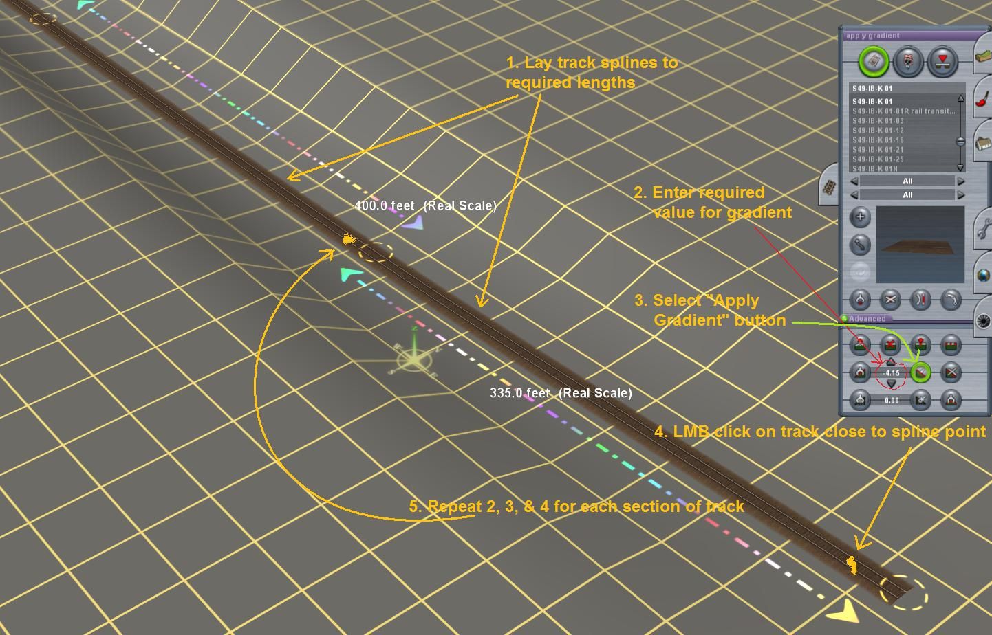
I am testing signals on a small section of track between two subway stations--the track plans I have state the downward slope as follows:

Station Chaining: Downward Slope:
19+00 to 22+35 (335') -4.15%
22+35 to 26+35 (400') -3.8%
26+35 to 29+49 (314') -4.5%
29+49 to 35+00 (551') -0.2%

I have no idea on where to start (my trig is very rusty!) and whether I put in those values in the box and apply them?

Any help is appreciated gentlemen!

-A :wave:
 
Most US mainlines are 1.75% or less, Saluda grade was well over 2%, certain logging and scenic RR's were aproaching 4%, the Mt Washington Cog Railway has rediculous gradients !

You would be best to keep it at 1.75% or much less (except for trolley and subway tracks, that can get quite steep).

When you type in 0.01% and touch just a hair ahead of the tracks lowest spline point circle, the opposite spline point circle farther down the track will raise. So you work your way up, applying the gradient to just slightly ahead of the next spline point circle, and the next one will rise higher. You can check your gradients on the minimap.

I like to keep my gradients @ 0.10% to 0.50% ... as 1.00% can get to be a bit of a steep gradient .

You will find that touching the center of the spline point circle will give you problems, so go just outside (ahead) of the spline point circle, and touch the track there. ---Ox---------------Ox-------------Ox---

When two single tracks (such as on a curve) are connected to a double track spline (such as on a straightaway), the double track spline has seniority over a single track and will not raise.

Raising multitrack splines is done by touching the area in the middle (between tracks), just ahead of the overlapping spline points.

I created a hump yard, with a track 125' long, with a -0.50% downhill gradient, and thereafter was -0.01% gradient (after several miles a rolling railcar will slowly come to a halt, as a 0.02% gradient is what trainz needs to be free rolling).

My longwinded pointers on gradients and curves could fill a book ... feel free to PM me.
 
Last edited:
The gradient tool uses % figures.

So measure out your lengths of track with the ruler. Make a spline in the track 335 feet away and so on according to your information. Set -4.15% in the gradient tool. Go back to the start point and work from the top, down the hill. Apply the gradient once to the track near the top spline. Do not ever apply the gradient to the track nearer to the next spline point - if you do the track will slope the opposite way to what you expect. Go to your spline point at 335 feet. Set grad tool to -3.8% and apply to next section of track and so on.
 
Hey stovepipe, you beat me to it whilst I was putting this image together.:D

I'll post it anyway.

The other thing to add is that this method assumes a straight track. If the tracks are curved you could make up a train to the required lengths. Measuring cars are available, although for the relatively short runs listed in the OP, that method probably isn't necessary.

Cheers
Casper

gradient_zpsa6e13782.jpg
 
Has anyone ever laid track from the Trainz minimum of -3000m, all the way up to +3000m ?
On a 1.75% grade that would take a zillion miles of trackage.

It would be like going from the Marianas Trench, up to Mt McKinley

I'm suprised that nobody has made a Mt Washington Cog Rwy route, Mt Tamalapais (read the book: The Crookedst RR in the West), or Mt Lowe route ... that would be a real gradient !
 
Last edited:
Thanks to Mezzo, Stovepipe and Cascader. Your information was really helpful! I'm a visual learner, so the picture really help! The test track itself is only 1,600 feet long, but this'll be for an entire subway/elevated route in NYC, so we'll see what happens on curved tracks.

I'll post some pictures once I get a chance.

Thanks again!

-A :wave:
 
On a side note.
Has anyone ever laid track from the Trainz minimum of -3000m, all the way up to +3000m ?
On a 1.75% grade that would take a zillion miles of trackage.
There is a route on the dls that does go from -3000m to 3000m. It it called Worldtop

It is the route I have been modifying for almost 8 Years.:) It has mostly 3.5 -4% grade. That is why I like it.
Kenny
 
Last edited:
Hate to bump the thread so many months later, but it seemed better than starting something over.

I believe I might have either misread or misused Mezzo's picture tutorials, because when comparing the rises and falls to at-ground-level images on Google Earth--parts of my el system seem ridiculously high compared to their real life counterparts. Also, I seem to have noticed a big difference when inputting -3 as opposed to -3.0 on the grades. Does the ".0" matter?

-A :wave:
 
If you have been getting spot heights from Google Earth then prepare to be disappointed. Whilst the GE lat/long positions are dazzlingly accurate, I have found some UK heights woefully adrift. A recent example was where I took a spot height from GE of a Triangulation Pillar on the Purbeck Hills, southern UK. The position and heights af these pillars are well documented and many (including the one I was measuring) can be seen on GE. The height offered by GE was too low, and the real height was placed at a lower point of the GE imagery some 250 feet distant. I know that the pillar is higher, I've walked the area several times.

I looked at three other examples in the area and GE shows the wrong height in each case. It's a real pain.


I've just tried the apparent -3 and -3.0 anomaly and can't see a problem. I've just laid two bits of level track, side by side, with five spline points. I then applied -3 to one, and -3.0 to the other, at each of the spline points. They both result in exactly the same incline.

Maybe you have applied one of the values on the wrong side of one of the spline points. The other possible error is that you have put your number in the Height value rather than the Gradient value box. I've done that more than once!
 
Maybe you're right. I'm trying to decipher your photo tutorial, and my mind is running in circles, so forgive me.

Using the examples in my OP, you're telling me that I lay the 335' track section, then run the 400' section, and then apply the gradient from the 335' section (-4.15%) and then LMB click just a little before the initial spline point? (Where your arrow from "4." points to?)

If I'm reading this correctly (let's pray to the content Gods that I am!), the gradient for the track section goes at the beginning of the block and not at end? If that's the case, then I have been doing it backwards for the last few months! (#headache!)

Thanks again for taking the time to read this and respond accordingly. I'm not bumping old threads, but merely updating when I'm running into problems!

-A :wave:
 
The following link may help others to determine the correct gradient value to insert in trains: http://www.trainman.id.au/grade.htm

To try to answer your question. You can insert the gradient figure at either end of any piece of track, just inside the spline point, as has been mentioned. If you put a positive value at one end, then the other end of the track will show a negative value, so there is nothing to stop you placing negative values yourself.

I have great difficulties with gradients myself. Obviously if it's a straight piece of track then it's a breeze - just make the track as long as possible and insert the gradient value. However, if you're trying to obtain a smooth gradient on a twisting railroad, where you have to use several pieces of track to get the curves correct, it becomes a struggle. I would like to see a tool where you can select two independent spline points and then insert a gradient setting between the two points. Too much maths involved for me because the distance of track has to be calculated but I'm sure a competent computer programmer could come up with an answer :confused:
 
The gradient tool is actually pretty straightforward. Consider the following 3 splines and 4 spline points.

A-----B--C-----D

To have straight track AB smoothly transit to straight gradient CD, BC is required as the "unstraightened" transition piece. Straighten track tool works very closely with gradient tool.
Assuming AB and CD have been straightened, if I want a 1 percent grade from CD all I have to do is click the intended lower half of that spline, if laying track conventionally (ie. up a hill). If going downhill then you will apply it on the intended upper half of that spline.

We could just leave it at that. But now you notice at BC dips a little. This is because points B and C are at the same height. In order to fix this, we must raise CD a little bit. We could do this manually by adding to the height values at CD, but this is troublesome if you have a few more spline points after that (ie. CDEF), so we let the gradient tool do this for us. If we add 1 to C and then apply the 1% gradient to the lower halves of CD, DE and EF, all of them will be raised by the same amount because the beginning of the gradient has been raised, effectively lifting the whole stretch of track.

Sometimes you may find two stretches of track having the exact same gradient value but displaying different characteristics, this is because gradient is affected by whether or not the spline and its neighboring splines are straightened. Here is a quote from an old post I wrote.

A (50)--------------------B (51.2)------C (51.7)-----------------D (53)

Assuming I'm smoothing B to C.
If B to C is a curve and AB, CD are straightened splines, A and D must be raised to 50.2 and 53.2 respectively or the middle of BC will be floating.

Non-straightened splines are affected by straightened ones not only in terms or curvature but also in elevation.

This takes practice, but a good rule of thumb is always to do such 'smoothing operations' which start and end at straightened splines. This way, the probability of you forgetting which ones you've smoothed/raised is lesser.

Cheerio,
Nicholas
 
Maybe you're right. I'm trying to decipher your photo tutorial, and my mind is running in circles, so forgive me.

Using the examples in my OP, you're telling me that I lay the 335' track section, then run the 400' section, and then apply the gradient from the 335' section (-4.15%) and then LMB click just a little before the initial spline point? (Where your arrow from "4." points to?)

If I'm reading this correctly (let's pray to the content Gods that I am!), the gradient for the track section goes at the beginning of the block and not at end? If that's the case, then I have been doing it backwards for the last few months! (#headache!)

Thanks again for taking the time to read this and respond accordingly. I'm not bumping old threads, but merely updating when I'm running into problems!

-A :wave:

Click just beyond the spline circle (roughly at the little squiggle mark I placed on the track at the end of the “4” arrow) and, with your minus value of -4.15, that spline circle will become the top of the slope on your 335’ section.

To set the incline on the next (400’) section, click beyond the next spline point roughly where the squiggle is at the end of the “5” arrow, but make sure you have re-set the value to -3.8

Then just move down the line to the next spline circle, which starts the 314’ section, enter the -4.5 value into the gradient value box and apply it just beyond the circle.

Move down to the last 551’ section and follows the same process using a -0.2 value.

I initially had problems getting my head around which end to apply negative or positive values, so invented a memory trick. I think of the minus sign as a skateboard which wants to go downhill, so the minus values always need to be at the top of the track segment.
 
Back
Top